Arduino UNO and Nano Based GPS Tracker with GSM and Sound Detection
Circuit Documentation
Summary
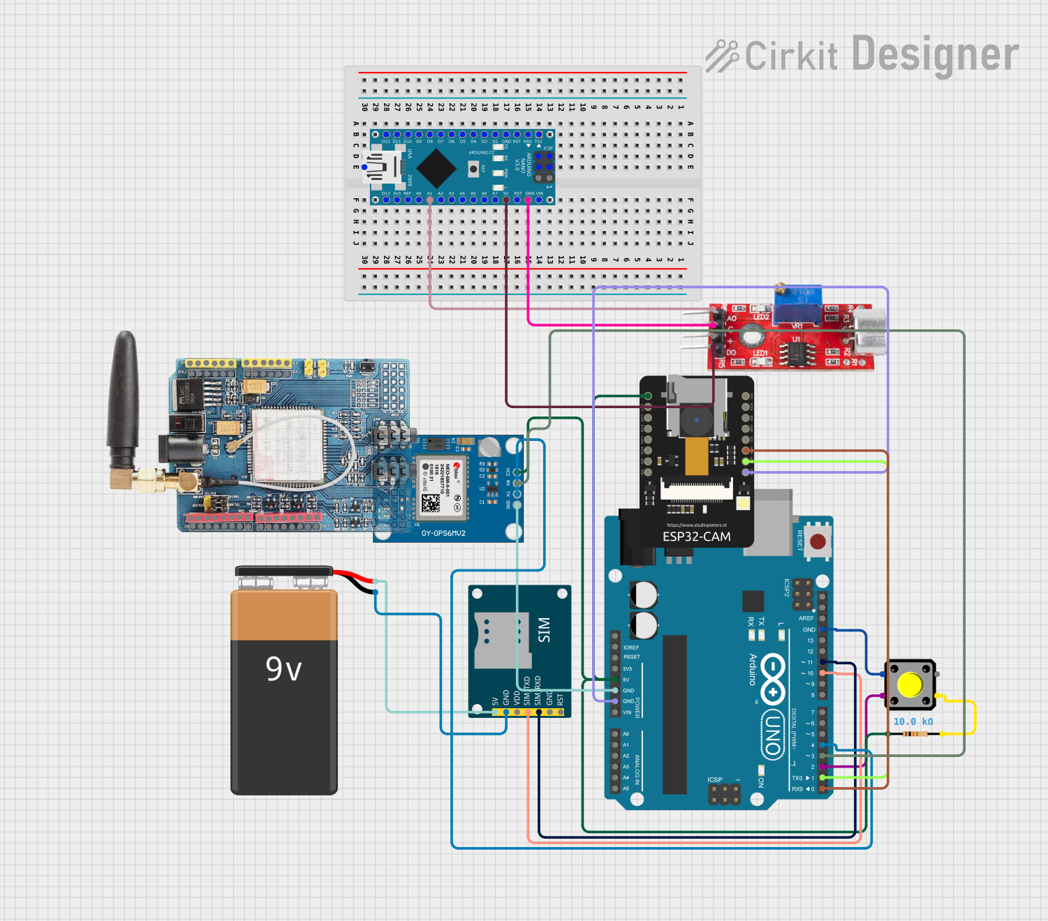
The circuit in question is designed to integrate various modules with an Arduino UNO microcontroller as the central processing unit. The circuit includes a pushbutton for user input, a SIM800L GSM module for cellular communication, a Neo 6M GPS module for location tracking, a sound sensor for audio detection, and an ESP32-CAM for wireless communication and camera functionalities. A resistor is used for pull-up configuration on the pushbutton, and a 9V battery provides power to the GSM module. The Arduino Nano and GSM SIM900 modules are also present in the parts list but are not integrated into the circuit based on the provided net list.
Component List
Arduino UNO
- Microcontroller board based on the ATmega328P
- Used as the main controller for the circuit
Pushbutton
- A simple switch mechanism for control of a circuit
- Used for user input to trigger actions
SIM800L GSM Module
- A complete Quad-band GSM/GPRS solution
- Used for cellular communication capabilities
Resistor
- A passive two-terminal electrical component
- Used to limit current flow and adjust signal levels
9V Battery
- A standard size of battery with a nominal voltage of 9V
- Used to provide power to the GSM module
Neo 6M GPS Module
- A GPS receiver module
- Used for obtaining geographical location data
Sound Sensor
- An audio detecting sensor with digital and analog outputs
- Used for detecting sound levels in the environment
ESP32-CAM
- A small-sized ESP32-based module with a camera
- Used for wireless communication and capturing images or video
Wiring Details
Arduino UNO
5Vconnected to the 5V power rail supplying power to other componentsGNDconnected to the ground railD11connected to SIM800L GSM ModuleSIM_RXDD10connected to SIM800L GSM ModuleSIM_TXDD4connected to Neo 6M GPS ModuleTXD3connected to Neo 6M GPS ModuleRXD2connected to one terminal of the PushbuttonD1connected to ESP32-CAMVOTD0connected to ESP32-CAMVOR
Pushbutton
- One terminal connected to Arduino UNO
D2 - Another terminal connected to one end of the Resistor (other end to GND)
SIM800L GSM Module
5Vconnected to 9V Battery+GNDconnected to 9V Battery-SIM_TXDconnected to Arduino UNOD10SIM_RXDconnected to Arduino UNOD11
Resistor
- One end connected to Pushbutton
- Other end connected to GND
9V Battery
+connected to SIM800L GSM Module5V-connected to SIM800L GSM ModuleGND
Neo 6M GPS Module
VCCconnected to 5V power railGNDconnected to ground railTXconnected to Arduino UNOD4RXconnected to Arduino UNOD3
Sound Sensor
VCCconnected to Arduino Nano5VGNDconnected to Arduino NanoGNDDigitalconnected to Arduino Nano5VAnalogconnected to Arduino NanoA1
ESP32-CAM
5Vconnected to 5V power railGNDconnected to ground railVOTconnected to Arduino UNOD1VORconnected to Arduino UNOD0
Documented Code
Arduino UNO Code
#include <SoftwareSerial.h>
#include <TinyGPS++.h>

// Define pin numbers
const int buttonPin = 2;  // Push button connected to digital pin 2
const int gsmRxPin = 10;  // RX pin of GSM module
const int gsmTxPin = 11;  // TX pin of GSM module
const int gpsRxPin = 4;   // RX pin of GPS module
const int gpsTxPin = 3;   // TX pin of GPS module

// Create software serial objects
SoftwareSerial gsmSerial(gsmRxPin, gsmTxPin);
SoftwareSerial gpsSerial(gpsRxPin, gpsTxPin);

// Create a TinyGPS++ object
TinyGPSPlus gps;

// Variables
int buttonState = 0;
bool messageSent = false;
const char* phoneNumber = "+1234567890";  // Replace with the desired phone number
const char* message = "Emergency! Help needed at this location: ";

void setup() {
  Serial.begin(9600);
  gsmSerial.begin(9600);
  gpsSerial.begin(9600);

  pinMode(buttonPin, INPUT_PULLUP);

  // Initialize GSM module
  delay(1000);
  gsmSerial.println("AT");
  delay(1000);
  gsmSerial.println("AT+CMGF=1"); // Set SMS text mode
  delay(1000);
}

void loop() {
  // Update GPS data
  while (gpsSerial.available() > 0) {
    gps.encode(gpsSerial.read());
  }

  buttonState = digitalRead(buttonPin);

  if (buttonState == LOW && !messageSent) {
    sendSMS();
    messageSent = true;
  }

  if (buttonState == HIGH) {
    messageSent = false;
  }
}

void sendSMS() {
  Serial.println("Button pressed, sending SMS with location...");

  String locationMessage = message;

  if (gps.location.isValid()) {
    locationMessage += "http://maps.google.com/maps?q=";
    locationMessage += String(gps.location.lat(), 6);
    locationMessage += ",";
    locationMessage += String(gps.location.lng(), 6);
  } else {
    locationMessage += "GPS location not available";
  }
}
Arduino Nano Code
void setup() {
  // put your setup code here, to run once:

}

void loop() {
  // put your main code here, to run repeatedly:

}
(Note: The Arduino Nano code provided is empty and does not perform any function in the current circuit configuration.)