
Arduino Nano-Based RFID Access Control System with IR Sensors and Feedback Indicators
View and Edit Project In Cirkit Designer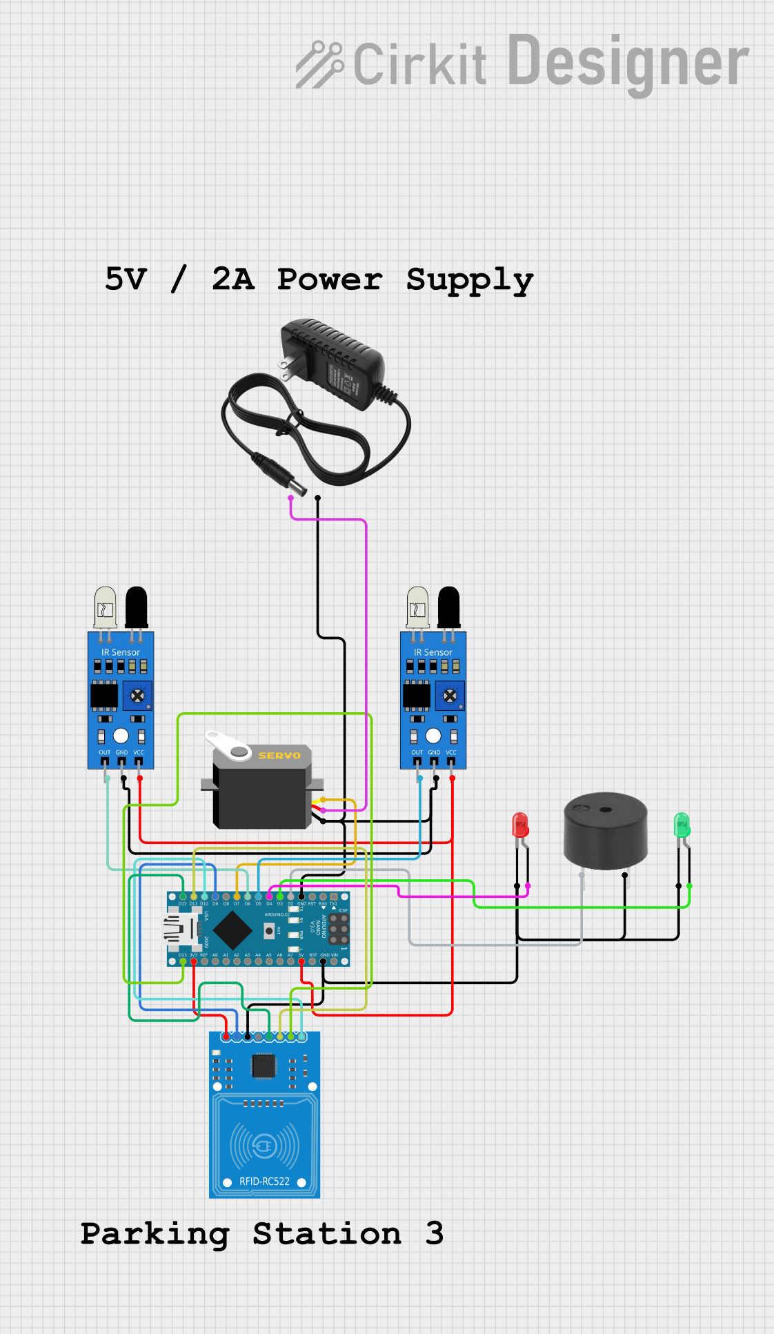
Circuit Documentation
Summary
This circuit integrates various components controlled by an Arduino Nano microcontroller. It includes a servo motor, a buzzer, two LEDs (red and green), two IR sensors, and an RFID-RC522 module. The circuit is powered by a 12V power supply, with the Arduino Nano regulating voltage for certain components. The IR sensors detect the presence or absence of objects, the RFID-RC522 module is used for RFID communication, the servo motor is controlled via PWM, and the LEDs and buzzer provide visual and auditory feedback, respectively.
Component List
Servo
- Description: A motor capable of precise position control.
- Pins: GND, VCC, Pulse
Buzzer
- Description: An audio signaling device.
- Pins: PIN, GND
LED: Two Pin (Red)
- Description: A red light-emitting diode.
- Pins: Cathode, Anode
LED: Two Pin (Green)
- Description: A green light-emitting diode.
- Pins: Cathode, Anode
IR Sensor
- Description: A sensor that detects infrared light, commonly used for object detection.
- Pins: Out, GND, VCC
Arduino Nano
- Description: A small, complete, and breadboard-friendly microcontroller board based on the ATmega328P.
- Pins: D1/TX, D0/RX, RESET, GND, D2, D3, D4, D5, D6, D7, D8, D9, D10, D11/MOSI, D12/MISO, VIN, 5V, A7, A6, A5, A4, A3, A2, A1, A0, AREF, 3V3, D13/SCK
RFID-RC522
- Description: A module used for RFID communication.
- Pins: SDA, SCK, MOSI, MISO, IRQ, GND, RST, 3.3V
12V Power Supply
- Description: A power source for the circuit.
- Pins: +, -
Wiring Details
Servo
- GND connected to common ground.
- VCC connected to the 12V power supply (+).
- Pulse connected to Arduino Nano pin D7.
Buzzer
- PIN connected to Arduino Nano pin D2.
- GND connected to common ground.
LED: Two Pin (Red)
- Cathode connected to common ground.
- Anode connected to Arduino Nano pin D4.
LED: Two Pin (Green)
- Cathode connected to common ground.
- Anode connected to Arduino Nano pin D3.
IR Sensor
- Out of the first IR sensor connected to Arduino Nano pin D6.
- Out of the second IR sensor connected to Arduino Nano pin D5.
- GND of both IR sensors connected to common ground.
- VCC of both IR sensors connected to Arduino Nano 5V.
Arduino Nano
- GND connected to common ground.
- 5V used to power IR sensors.
- 3V3 used to power RFID-RC522 module.
- D2, D3, D4, D5, D6, D7 used for interfacing with components.
- D10, D11/MOSI, D12/MISO, D13/SCK used for interfacing with RFID-RC522.
RFID-RC522
- SDA connected to Arduino Nano pin D10.
- SCK connected to Arduino Nano pin D13/SCK.
- MOSI connected to Arduino Nano pin D11/MOSI.
- MISO connected to Arduino Nano pin D12/MISO.
- GND connected to common ground.
- RST connected to Arduino Nano pin D9.
- 3.3V connected to Arduino Nano 3V3.
12V Power Supply
- (+) connected to Servo VCC.
- (-) connected to common ground.
Documented Code
void setup() {
  // put your setup code here, to run once:

}

void loop() {
  // put your main code here, to run repeatedly:

}
Filename: sketch.ino
Note: The provided code is a template and does not contain any functional code. It needs to be populated with instructions to control the components as per the circuit's requirements.