Cirkit Designer
Your all-in-one circuit design IDE
Home /
Project Documentation
ESP32-Based Temperature and Humidity Monitoring System
Circuit Documentation
Summary of the Circuit
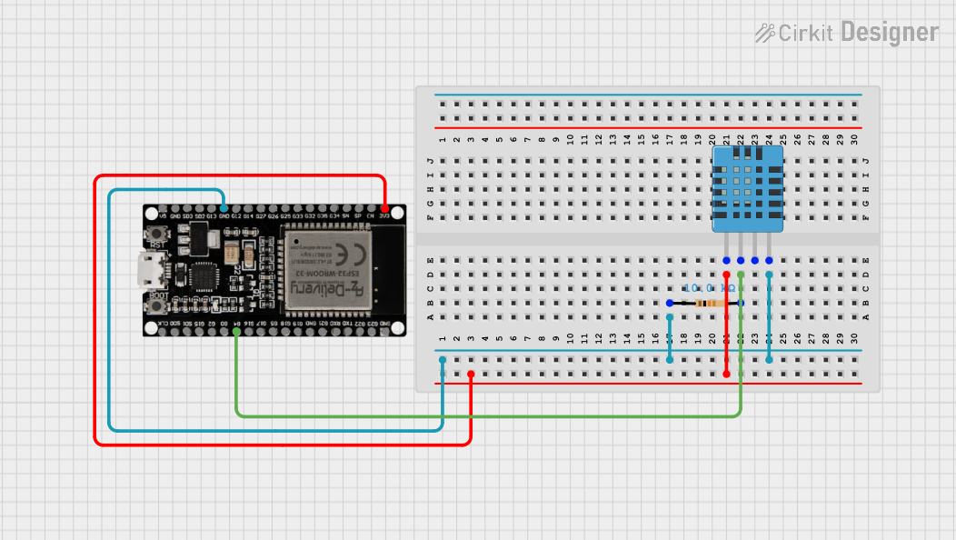
This circuit integrates a DHT11 Humidity and Temperature Sensor with an ESP32 microcontroller and includes a resistor for potential voltage division or pull-up/down purposes. The ESP32 reads data from the DHT11 sensor, which can be used to monitor environmental conditions. The circuit is powered by the ESP32's 3.3V output, and the sensor's data line is connected to the ESP32 through a resistor, which may serve as a pull-up resistor.
Component List
Resistor
- Description: A passive two-terminal electrical component that implements electrical resistance as a circuit element.
- Purpose: Typically used for creating voltage drops or limiting current. In this circuit, it may be used as a pull-up resistor for the data line of the DHT11 sensor.
- Properties:
- Resistance: 10,000 Ohms
ESP32 38 PINS
- Description: A microcontroller with Wi-Fi and Bluetooth capabilities, featuring a wide range of GPIO pins.
- Purpose: Acts as the central processing unit of the circuit, reading sensor data and potentially communicating it wirelessly.
- Properties:
- 38 GPIO pins including power, digital, analog, UART, SPI, and other communication interfaces.
DHT11 Humidity and Temperature Sensor
- Description: A basic, low-cost digital temperature and humidity sensor.
- Purpose: Measures the surrounding air temperature and humidity.
- Properties:
- Operates on 3 to 5V power
- Provides digital signal output
Wiring Details
Resistor
- Pin 1: Connected to the GND of the DHT11 sensor and GND of the ESP32.
- Pin 2: Connected to the DATA pin of the DHT11 sensor and GPIO 4 (G4) of the ESP32.
ESP32 38 PINS
- GND: Connected to the GND pin of the DHT11 sensor and Pin 1 of the Resistor.
- 3V3: Provides power to the VDD pin of the DHT11 sensor.
- G4: Receives the data signal from the DHT11 sensor through the Resistor.
DHT11 Humidity and Temperature Sensor
- VDD: Powered by the 3V3 pin of the ESP32.
- DATA: Sends data to the ESP32's GPIO 4 (G4) through the Resistor.
- GND: Connected to the GND of the ESP32 and Pin 1 of the Resistor.
Documented Code
sketch.ino
void setup() {
  // put your setup code here, to run once:

}

void loop() {
  // put your main code here, to run repeatedly:

}
documentation.txt
(No additional documentation provided for the code)
This documentation provides an overview of the circuit's components, their connections, and the initial code structure for the ESP32 microcontroller. Further development of the code is required to initialize the sensor and process its data.