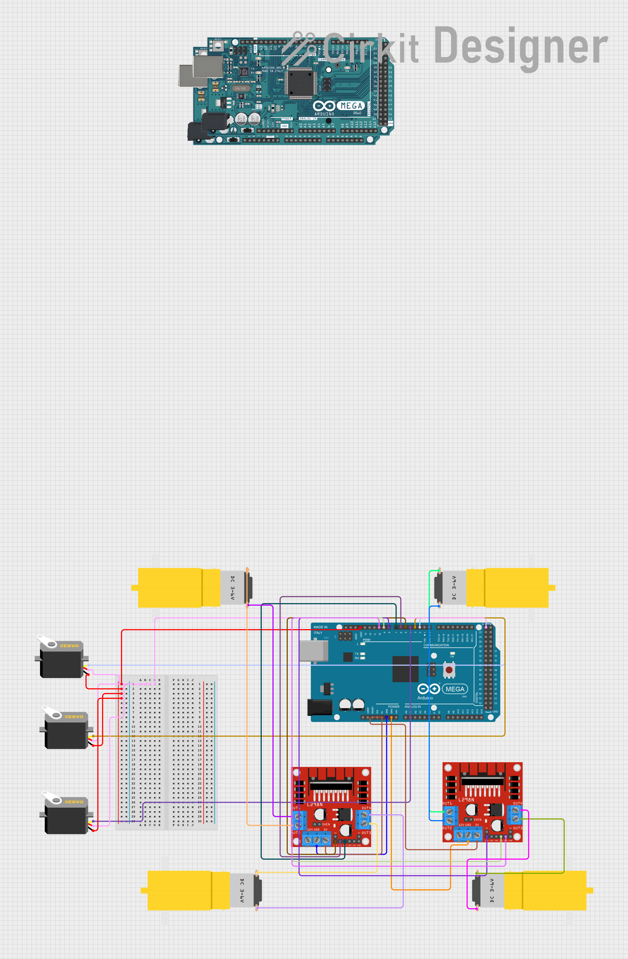
Arduino Mega 2560 Controlled Servo and DC Motor System

Circuit Documentation
Summary
The circuit in question appears to be designed for controlling multiple DC motors and servos using two Arduino Mega 2560 microcontrollers and two L298N DC motor drivers. The servos are directly controlled by the PWM outputs of one Arduino, while the DC motors are interfaced through the L298N motor drivers. The circuit includes power distribution for the components and signal connections for control.
Component List
Microcontrollers
- Arduino Mega 2560: A microcontroller board based on the ATmega2560, with a wide range of input/output pins, including PWM, digital, and analog pins.
Motors
- Servo: A rotary actuator or linear actuator that allows for precise control of angular or linear position, velocity, and acceleration.
- Motor amarillo motorreductor hobby: A yellow DC gear motor commonly used for hobby projects.
Motor Drivers
- L298N DC motor driver: A dual H-bridge motor driver capable of driving two DC motors or one stepper motor.
Wiring Details
Arduino Mega 2560
- 5V: Connected to the 5V pins of both L298N motor drivers and all servos to provide power.
- GND: Connected to the GND pins of both L298N motor drivers and all servos to provide a common ground.
- D2 PWM - D10 PWM: PWM outputs connected to servo pulse inputs and L298N control inputs (ENA, IN1, IN2, ENB, IN3, IN4) for motor speed and direction control.
Servos
- Pulse: Connected to the corresponding PWM pins on the Arduino Mega 2560 for control signals.
- VCC: Connected to the 5V output from the Arduino Mega 2560.
- GND: Connected to the ground on the Arduino Mega 2560.
Motor amarillo motorreductor hobby
- VCC: Connected to the OUT1 and OUT3 of the L298N motor drivers for motor power.
- GND: Connected to the OUT2 and OUT4 of the L298N motor drivers to complete the motor circuit.
L298N DC motor driver
- 5V: Receives power from the Arduino Mega 2560.
- GND: Connected to the ground on the Arduino Mega 2560.
- ENA, ENB: Enable pins for motor channels, connected to PWM outputs on the Arduino Mega 2560.
- IN1, IN2, IN3, IN4: Input pins for controlling motor direction, connected to digital outputs on the Arduino Mega 2560.
- OUT1, OUT2, OUT3, OUT4: Output pins connected to the DC motors.
Documented Code
Arduino Mega 2560 - Main Controller
void setup() {
  // put your setup code here, to run once:

}

void loop() {
  // put your main code here, to run repeatedly:

}
This code is a template and does not contain any specific functionality. It should be populated with initialization code in setup() and the main control logic in loop() to control the servos and DC motors based on the desired application.
Additional Microcontrollers
The additional Arduino Mega 2560 units in the circuit have the same template code as the main controller. Each Arduino should be programmed with specific tasks to handle different parts of the circuit or to work in parallel with the main controller for complex tasks.
This documentation provides an overview of the circuit, the components used, their wiring, and the base code for the microcontrollers. Further details should be added to the code sections to reflect the actual control logic for the motors and servos.