
Raspberry Pi Pico W Controlled RGB LED with Joystick Interaction
View and Edit Project In Cirkit Designer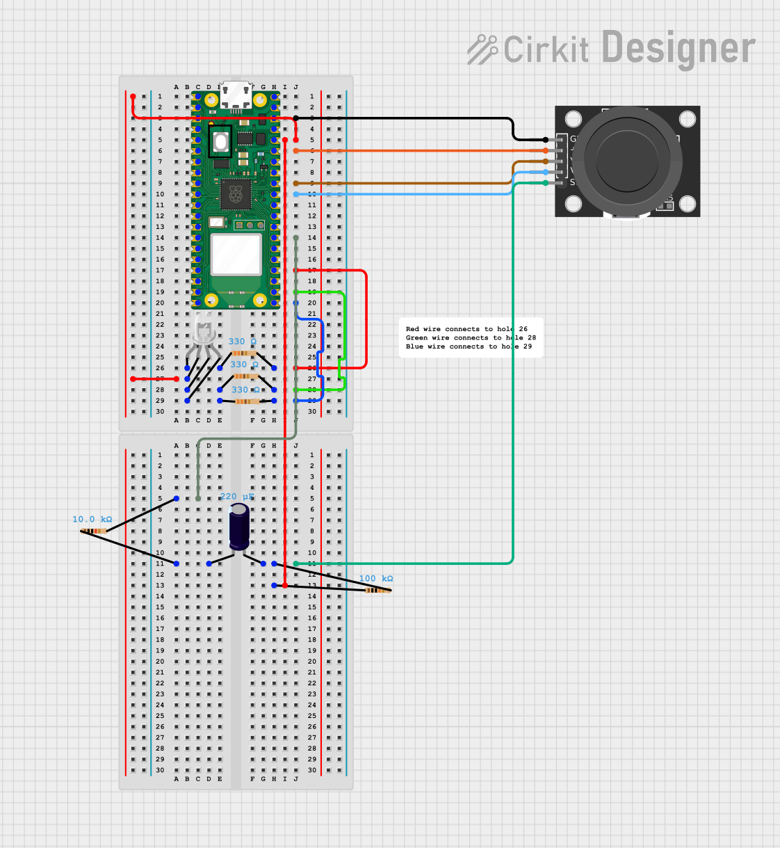
Circuit Documentation
Summary
This circuit is designed to interface a Raspberry Pi Pico W with a KY-023 Dual Axis Joystick Module and a multi-color LED with four pins (common anode configuration). The circuit includes several resistors to limit current and an electrolytic capacitor for debouncing the joystick button. The Raspberry Pi Pico W is programmed to read the joystick's position and to control the brightness and color of the LED based on the joystick's input.
Component List
LED: Four Pin
- Description: A multi-color LED with separate cathodes for red, green, and blue colors and a common anode.
- Purpose: To display various colors by adjusting the PWM signals to each cathode.
Resistor (330 Ohms)
- Description: A resistor with a resistance of 330 Ohms.
- Purpose: To limit the current flowing through the LED's cathodes, preventing damage to the LED.
Resistor (10 kOhms)
- Description: A resistor with a resistance of 10 kOhms.
- Purpose: Typically used for pull-up or pull-down resistors in digital circuits.
Resistor (100 kOhms)
- Description: A resistor with a resistance of 100 kOhms.
- Purpose: Often used for timing circuits or as a part of voltage dividers.
Electrolytic Capacitor (0.00022 Farads)
- Description: An electrolytic capacitor with a capacitance of 0.00022 Farads.
- Purpose: To debounce the joystick button press, providing a stable signal transition.
Raspberry Pi Pico W
- Description: A microcontroller board based on the RP2040 microcontroller, featuring Wi-Fi connectivity.
- Purpose: To serve as the central processing unit of the circuit, reading sensor data and controlling the LED.
KY-023 Dual Axis Joystick Module
- Description: A module with a two-axis joystick and a push button.
- Purpose: To provide user input for controlling the LED's color and brightness.
Wiring Details
LED: Four Pin
- Red cathode connected to a 330 Ohm resistor.
- Green cathode connected to a 330 Ohm resistor.
- Blue cathode connected to a 330 Ohm resistor.
- Common anode connected to the Raspberry Pi Pico W (pin 36) through a 100 kOhm resistor.
Resistor (330 Ohms)
- One side connected to the corresponding LED cathode.
- The other side connected to the Raspberry Pi Pico W (pins 21, 22, 24 for red, green, and blue cathodes respectively).
Resistor (10 kOhms)
- One side connected to the Raspberry Pi Pico W (pin 27).
- The other side connected to the negative side of the electrolytic capacitor.
Resistor (100 kOhms)
- One side connected to the Raspberry Pi Pico W (pin 36).
- The other side connected to the common anode of the LED.
Electrolytic Capacitor (0.00022 Farads)
- Positive side connected to the Raspberry Pi Pico W (pin 36) through a 100 kOhm resistor.
- Negative side connected to the Raspberry Pi Pico W (pin 27) through a 10 kOhm resistor.
Raspberry Pi Pico W
- Pin 38 connected to the GND of the KY-023 Joystick Module.
- Pin 35 connected to the +5V of the KY-023 Joystick Module.
- Pin 32 connected to the VRx of the KY-023 Joystick Module.
- Pin 31 connected to the VRy of the KY-023 Joystick Module.
- Pins 21, 22, 24, 27, 36 connected to the corresponding components as described above.
KY-023 Dual Axis Joystick Module
- GND connected to the Raspberry Pi Pico W (pin 38).
- +5V connected to the Raspberry Pi Pico W (pin 35).
- VRx connected to the Raspberry Pi Pico W (pin 32).
- VRy connected to the Raspberry Pi Pico W (pin 31).
- SW connected to the positive side of the electrolytic capacitor.
Documented Code
main.py
## main.py

#include modules
from machine import Timer, ADC, PWM
from utime import sleep
import rainbow

# declaring objects from PWM and ADC classes
joystickY = ADC(26)
redLED = PWM(18, freq=100, duty_u16=0, invert=1)
greenLED = PWM(17, freq=100, duty_u16=0, invert=1)
blueLED = PWM(16, freq=100, duty_u16=0, invert=1)

while True:
    valueY = joystickY.read_u16()
    rainbow.RGB(valueY, redLED, greenLED, blueLED, joystickY)
    sleep(.01)  # in seconds
rainbow.py
# rainbow.py contains the definitions for the RGB function and the forward and backward sequences.
# The code for rainbow.py is not provided here but should be saved with a .py extension.
documentation.txt
main.ino is the main.py program
rainbow.py.txt is the rainbow.py program

save these as .py extensions only
sketch.ino
# sketch.ino contains the logic for the color transitions and the joystick interaction.
# The code for sketch.ino is not provided here but should be saved with a .py extension.
Note: The provided code snippets are written in Python and are intended to be used with the Raspberry Pi Pico W's MicroPython environment. The file extensions mentioned in the documentation (.ino) are typically associated with Arduino sketches, which may be a mistake in the documentation. The correct file extension for MicroPython scripts is .py.