Cirkit Designer
Your all-in-one circuit design IDE
Home /
Project Documentation
Wi-Fi Controlled RFID-Based Smart Socket with LCD Display Using ESP8266
Circuit Documentation
Summary
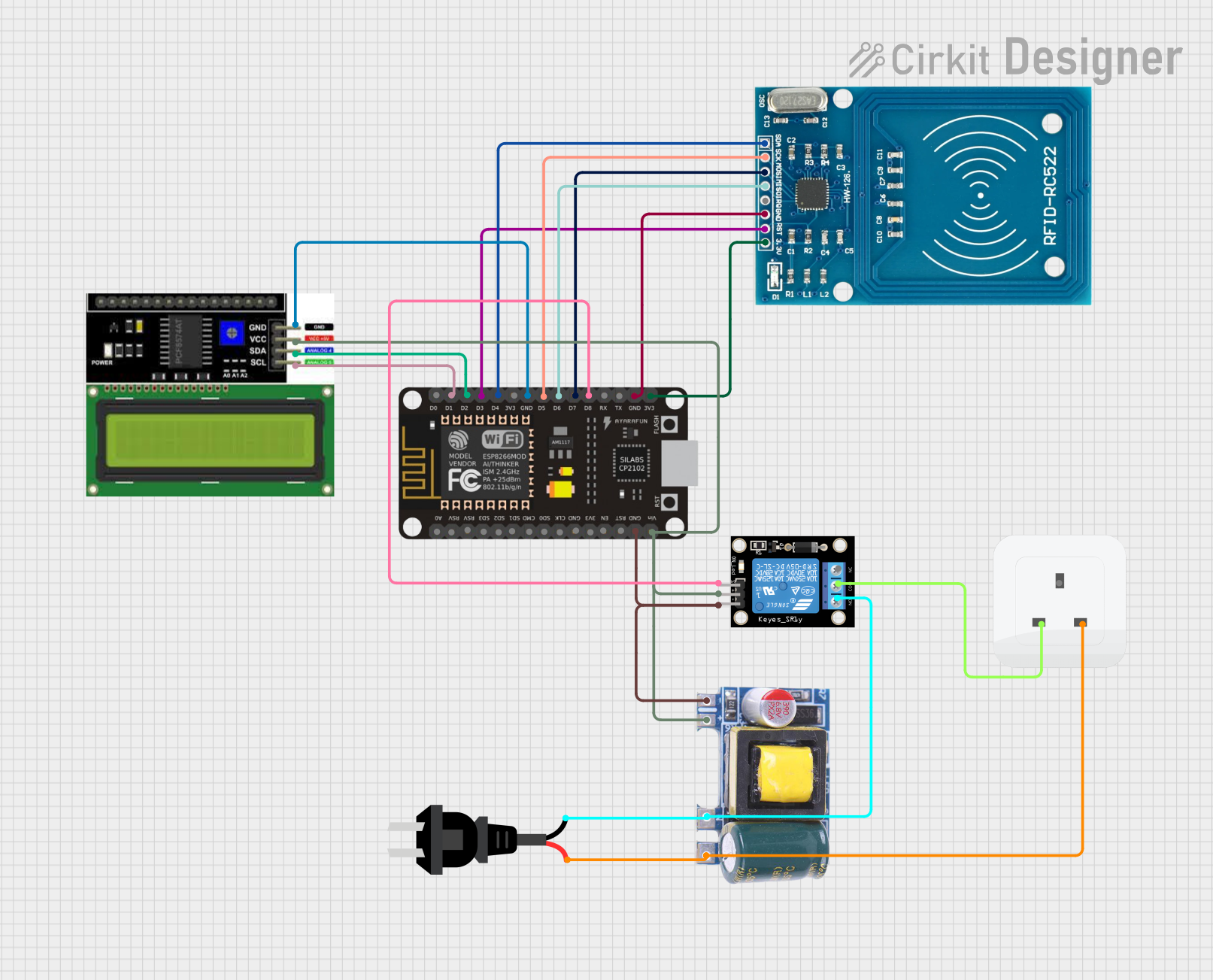
This circuit is designed to integrate an ESP8266 NodeMCU microcontroller with an LCD I2C Display, an RFID-RC522 module, a relay module, and a socket. The circuit also includes a Mini AC-DC 110V-230V to 5V 700mA module for power conversion and an AC source. The primary function of this circuit is to read RFID cards, display information on the LCD, and control a relay based on the RFID card data.
Component List
ESP8266 NodeMCU
- Description: A low-cost Wi-Fi microcontroller with GPIO, PWM, ADC, I2C, and SPI capabilities.
- Pins: D0, D1, D2, D3, D4, 3V3, GND, D5, D6, D7, D8, RX, TX, A0, RSV, SD3, SD2, SD1, CMD, SD0, CLK, EN, RST, VIN
LCD I2C Display
- Description: A 16x2 character LCD display with I2C interface.
- Pins: GND, VCC, SDA, SCL
RFID-RC522
- Description: A low-cost RFID reader module that operates at 13.56 MHz.
- Pins: VCC (3.3V), RST, GND, IRQ, MISO, MOSI, SCK, SDA
Relay Module 1 Channel
- Description: A single-channel relay module used for switching high voltage devices.
- Pins: S, 5V, GND, NC, COM, NO
Socket
- Description: A standard electrical socket.
- Pins: Earth, Life, Neutral
Mini AC-DC 110V-230V to 5V 700mA Module
- Description: A power module that converts AC voltage (110V-230V) to 5V DC.
- Pins: GND, 5V, Neutral, Life
AC Source
- Description: An AC power source.
- Pins: -, +
Wiring Details
ESP8266 NodeMCU
- D1: Connected to SCL of LCD I2C Display
- D2: Connected to SDA of LCD I2C Display
- D3: Connected to RST of RFID-RC522
- D4: Connected to SDA of RFID-RC522
- D5: Connected to SCK of RFID-RC522
- D6: Connected to MISO of RFID-RC522
- D7: Connected to MOSI of RFID-RC522
- D8: Connected to S of Relay Module 1 Channel
- GND: Connected to GND of LCD I2C Display, GND of RFID-RC522, and GND of Mini AC-DC 110V-230V to 5V 700mA Module
- 3V3: Connected to VCC (3.3V) of RFID-RC522
- VIN: Connected to 5V of Mini AC-DC 110V-230V to 5V 700mA Module
LCD I2C Display
- GND: Connected to GND of ESP8266 NodeMCU
- VCC: Connected to 5V of Mini AC-DC 110V-230V to 5V 700mA Module
- SDA: Connected to D2 of ESP8266 NodeMCU
- SCL: Connected to D1 of ESP8266 NodeMCU
RFID-RC522
- VCC (3.3V): Connected to 3V3 of ESP8266 NodeMCU
- RST: Connected to D3 of ESP8266 NodeMCU
- GND: Connected to GND of ESP8266 NodeMCU
- SCK: Connected to D5 of ESP8266 NodeMCU
- MISO: Connected to D6 of ESP8266 NodeMCU
- MOSI: Connected to D7 of ESP8266 NodeMCU
- SDA: Connected to D4 of ESP8266 NodeMCU
Relay Module 1 Channel
- S: Connected to D8 of ESP8266 NodeMCU
- 5V: Connected to 5V of Mini AC-DC 110V-230V to 5V 700mA Module
- GND: Connected to GND of Mini AC-DC 110V-230V to 5V 700mA Module
- COM: Connected to Life of Socket
- NO: Connected to Neutral of Mini AC-DC 110V-230V to 5V 700mA Module and - of AC Source
Socket
- Life: Connected to COM of Relay Module 1 Channel
- Neutral: Connected to Life of Mini AC-DC 110V-230V to 5V 700mA Module
Mini AC-DC 110V-230V to 5V 700mA Module
- GND: Connected to GND of Relay Module 1 Channel and GND of ESP8266 NodeMCU
- 5V: Connected to 5V of Relay Module 1 Channel, VCC of LCD I2C Display, and VIN of ESP8266 NodeMCU
- Neutral: Connected to NO of Relay Module 1 Channel and - of AC Source
- Life: Connected to + of AC Source and Neutral of Socket
AC Source
- -: Connected to Neutral of Mini AC-DC 110V-230V to 5V 700mA Module and NO of Relay Module 1 Channel
- +: Connected to Life of Mini AC-DC 110V-230V to 5V 700mA Module
Documented Code
Main Code (sketch.ino)
#include <SPI.h>
#include <MFRC522.h>
#include <Wire.h>
#include <LiquidCrystal_I2C.h>
#include <ESP8266WiFi.h>
#include "User.h"
#include "LibHelper.h"

#define SS_PIN D4 // SDA
#define RST_PIN D3 // RST

MFRC522 rfid(SS_PIN, RST_PIN);
LiquidCrystal_I2C lcd(0x27, 16, 2); // Set the LCD address to 0x27 for a 16 chars and 2 lines display

const char* ssid = "MGTech IT Solutions";
const char* password = "mgtech2020";
// const char* ssid = "Excel";
// const char* password = "tanginamo";

unsigned long previousMillis = 0; // Stores the last time x was printed

bool isConnected = false;
String rfidUID = "";
bool cardPresent = false;
bool cardAccepted = false;
volatile unsigned long cardPulseTime;

String LCDTop = "";
String LCDBot = "";

unsigned long startTime = 0;
unsigned long elapsedTime = 0;
int seconds = 0;
int minutes = 0;
int hours = 0;
int previousSeconds = -1;
int previousMinutes = -1;
int previousHours = -1;

int credits = 0;
int creditTime = 0;

void connectToWiFi() {
  WiFi.begin(ssid, password);

  // Keep trying to connect until successful
  while (WiFi.status() != WL_CONNECTED) {
    delay(1000);
    Serial.print(".");
  }

  // Connection successful
  Serial.println("");
  Serial.println("Wi-Fi connected");
  Serial.println("IP address: ");
  Serial.println(WiFi.localIP());

  setLCDText("WiFi Connected", WiFi.localIP().toString());

  previousMillis = millis();
}

void setup() {
  Serial.begin(115200);
  SPI.begin();
  rfid.PCD_Init();

  lcd.init();
  lcd.backlight();

  setLCDText("Connecting WiFi", " ");
  Serial.print("Connecting WiFi");

  connectToWiFi();
}

void loop() {
  checkWifi();
  checkRFID();

  if (cardPresent && cardAccepted) {
    timeLoop();
  }

  delay(100);
}

void checkWifi() {
  unsigned long currentMillis = millis(); // Get the current time
  if (currentMillis - previousMillis >= 500