Cirkit Designer
Your all-in-one circuit design IDE
Home /
Project Documentation
ESP32-Based Fire Detection and Suppression System with DC Motors and IR Sensors
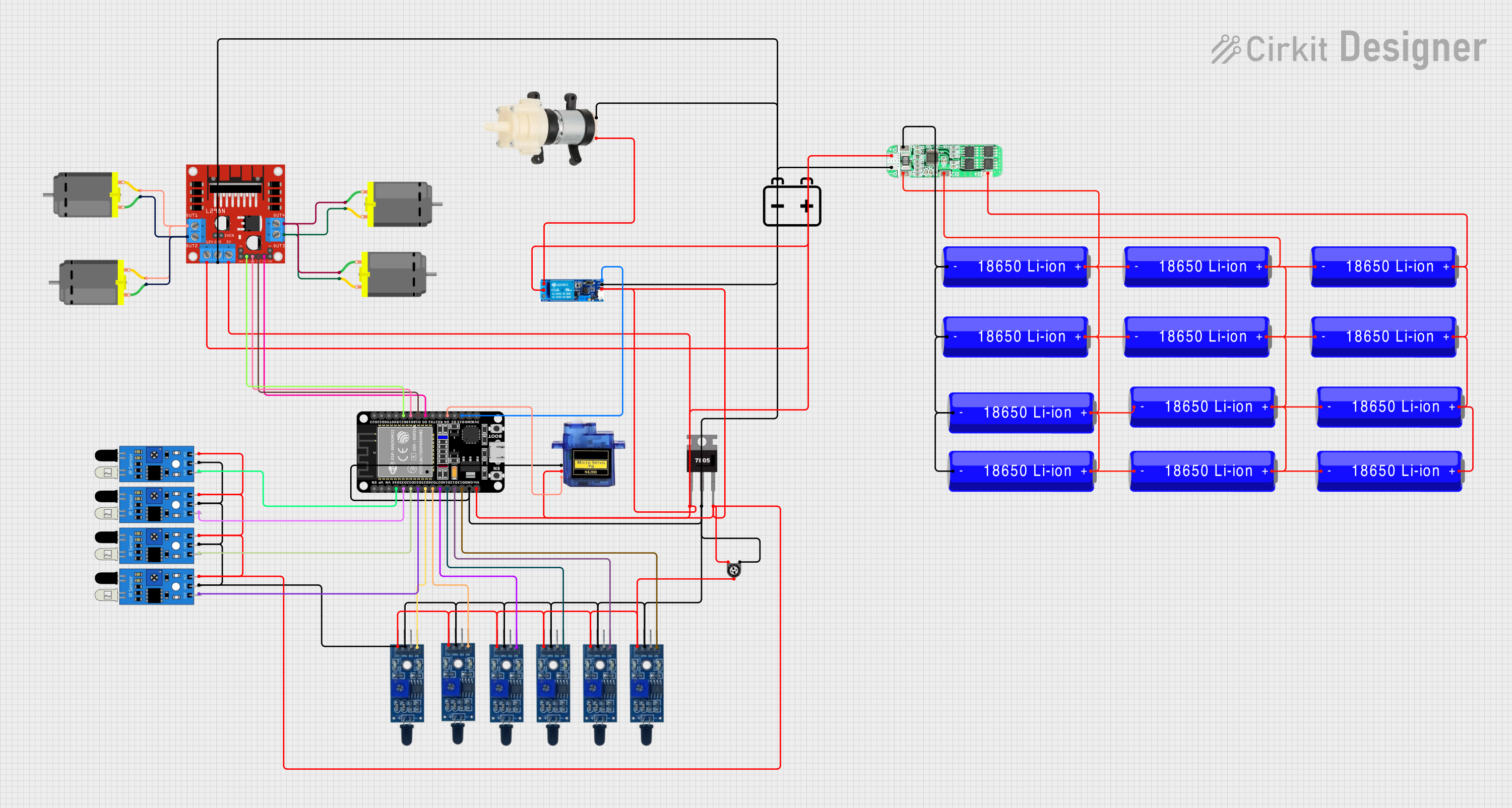
Circuit Documentation
Summary
This circuit is designed to control multiple DC motors, flame sensors, IR sensors, a micro servo, and a mini diaphragm water pump using an ESP32 microcontroller. The circuit also includes a relay module, a trimmer potentiometer, a 7805 voltage regulator, and a 3S 10A Li-ion 18650 Charger Protection Board Module. The power supply is provided by a 12V battery and multiple 18650 Li-ion batteries.
Component List
DC Motor
- Pins: pin 1, pin 2
- Description: A motor that converts electrical energy into mechanical energy.
- Purpose: Used to drive mechanical components.
Flame Sensor
- Pins: VCC, GND, D0, A0
- Description: A sensor that detects the presence of flame.
- Purpose: Used to detect fire or flame.
Trimmer Potentiometer
- Pins: leg1, wiper, leg2
- Description: A variable resistor used to adjust voltage.
- Purpose: Used to fine-tune the voltage in the circuit.
- Properties: Resistance: 10000 Ohms
IR Sensor
- Pins: out, gnd, vcc
- Description: An infrared sensor used to detect objects.
- Purpose: Used for object detection.
L298N DC Motor Driver
- Pins: OUT1, OUT2, 12V, GND, 5V, OUT3, OUT4, 5V-ENA-JMP-I, 5V-ENA-JMP-O, +5V-J1, +5V-J2, ENA, IN1, IN2, IN3, IN4, ENB
- Description: A dual H-bridge motor driver.
- Purpose: Used to control the speed and direction of DC motors.
7805 Voltage Regulator
- Pins: Vin, Gnd, Vout
- Description: A voltage regulator that outputs a constant 5V.
- Purpose: Used to provide a stable 5V power supply.
ESP32 (30 pin)
- Pins: EN, VP, VN, D34, D35, D32, D33, D25, D26, D27, D14, D12, D13, GND, Vin, D23, D22, TX0, RX0, D21, D19, D18, D5, TX2, RX2, D4, D2, D15, 3V3
- Description: A microcontroller with Wi-Fi and Bluetooth capabilities.
- Purpose: Used to control the entire circuit.
Relay Module 5V-30V
- Pins: common contact, normally open, normally closed, trigger, V-, V+
- Description: An electrically operated switch.
- Purpose: Used to control high voltage devices.
Mini Diaphragm Water Pump
- Pins: Positive (+), Negative (-)
- Description: A small water pump.
- Purpose: Used to pump water.
18650 Li-ion Battery
- Pins: -, +
- Description: A rechargeable lithium-ion battery.
- Purpose: Used to provide power to the circuit.
3S 10A Li-ion 18650 Charger Protection Board Module
- Pins: B+, B2, B1, P-, P+, B-
- Description: A protection board for charging 18650 Li-ion batteries.
- Purpose: Used to protect and charge the batteries.
12V Battery
- Pins: -, +
- Description: A 12V battery.
- Purpose: Used to provide power to the circuit.
Micro Servo 9G
- Pins: GND, +5V, PWM
- Description: A small servo motor.
- Purpose: Used for precise control of angular position.
Wiring Details
DC Motor
- pin 1 connected to L298N DC motor driver OUT2
- pin 2 connected to L298N DC motor driver OUT1
DC Motor
- pin 1 connected to L298N DC motor driver OUT4
- pin 2 connected to L298N DC motor driver OUT3
Flame Sensor
- VCC connected to Trimmer Potentiometer wiper
- GND connected to Common Ground
- A0 connected to ESP32 D13
Flame Sensor
- VCC connected to Trimmer Potentiometer wiper
- GND connected to Common Ground
- A0 connected to ESP32 D12
Flame Sensor
- VCC connected to Trimmer Potentiometer wiper
- GND connected to Common Ground
- A0 connected to ESP32 D14
Flame Sensor
- VCC connected to Trimmer Potentiometer wiper
- GND connected to Common Ground
- A0 connected to ESP32 D27
Flame Sensor
- VCC connected to Trimmer Potentiometer wiper
- GND connected to Common Ground
- A0 connected to ESP32 D25
Flame Sensor
- VCC connected to Trimmer Potentiometer wiper
- GND connected to Common Ground
- A0 connected to ESP32 D26
Flame Sensor
- VCC connected to Trimmer Potentiometer wiper
- GND connected to Common Ground
- A0 connected to ESP32 D35
Trimmer Potentiometer
- leg1 connected to Relay module 5v-30v V-
- leg2 connected to Relay module 5v-30v common contact
- wiper connected to Flame Sensor VCC
IR Sensor
- vcc connected to Common 12V
- gnd connected to Common Ground
- out connected to ESP32 D34
IR Sensor
- vcc connected to Common 12V
- gnd connected to Common Ground
- out connected to ESP32 D32
IR Sensor
- vcc connected to Common 12V
- gnd connected to Common Ground
- out connected to ESP32 D33
IR Sensor
- vcc connected to Common 12V
- gnd connected to Common Ground
- out connected to ESP32 D35
L298N DC Motor Driver
- OUT1 connected to DC Motor pin 2
- OUT2 connected to DC Motor pin 1
- OUT3 connected to DC Motor pin 2
- OUT4 connected to DC Motor pin 1
- 12V connected to Common 12V
- GND connected to Common Ground
- 5V connected to Common 5V
- IN1 connected to ESP32 D21
- IN2 connected to ESP32 D19
- IN3 connected to ESP32 D18
- IN4 connected to ESP32 D5
7805 Voltage Regulator
- Vin connected to Common 12V
- Gnd connected to Common Ground
- Vout connected to Common 5V
ESP32 (30 pin)
- Vin connected to Common 12V
- GND connected to Common Ground
- D21 connected to L298N DC motor driver IN1
- D19 connected to L298N DC motor driver IN2
- D18 connected to L298N DC motor driver IN3
- D5 connected to L298N DC motor driver IN4
- D34 connected to IR Sensor out
- D35 connected to IR Sensor out
- D32 connected to IR Sensor out
- D33 connected to IR Sensor out
- D25 connected to Flame Sensor A0
- D26 connected to Flame Sensor A0
- D27 connected to Flame Sensor A0
- D14 connected to Flame Sensor A0
- D12 connected to Flame Sensor A0
- D13 connected to Flame Sensor A0
- D4 connected to Micro servo 9G PWM
- D15 connected to Relay module 5v-30v trigger
Relay Module 5V-30V
- common contact connected to Trimmer Potentiometer leg2
- normally open connected to Mini Diaphragm Water Pump Positive (+)
- V- connected to Trimmer Potentiometer leg1
- V+ connected to Common 12V
- trigger connected to **