
Arduino 101 Wi-Fi Controlled Robotic Car with NRF24L01 and L298N Motor Driver
View and Edit Project In Cirkit Designer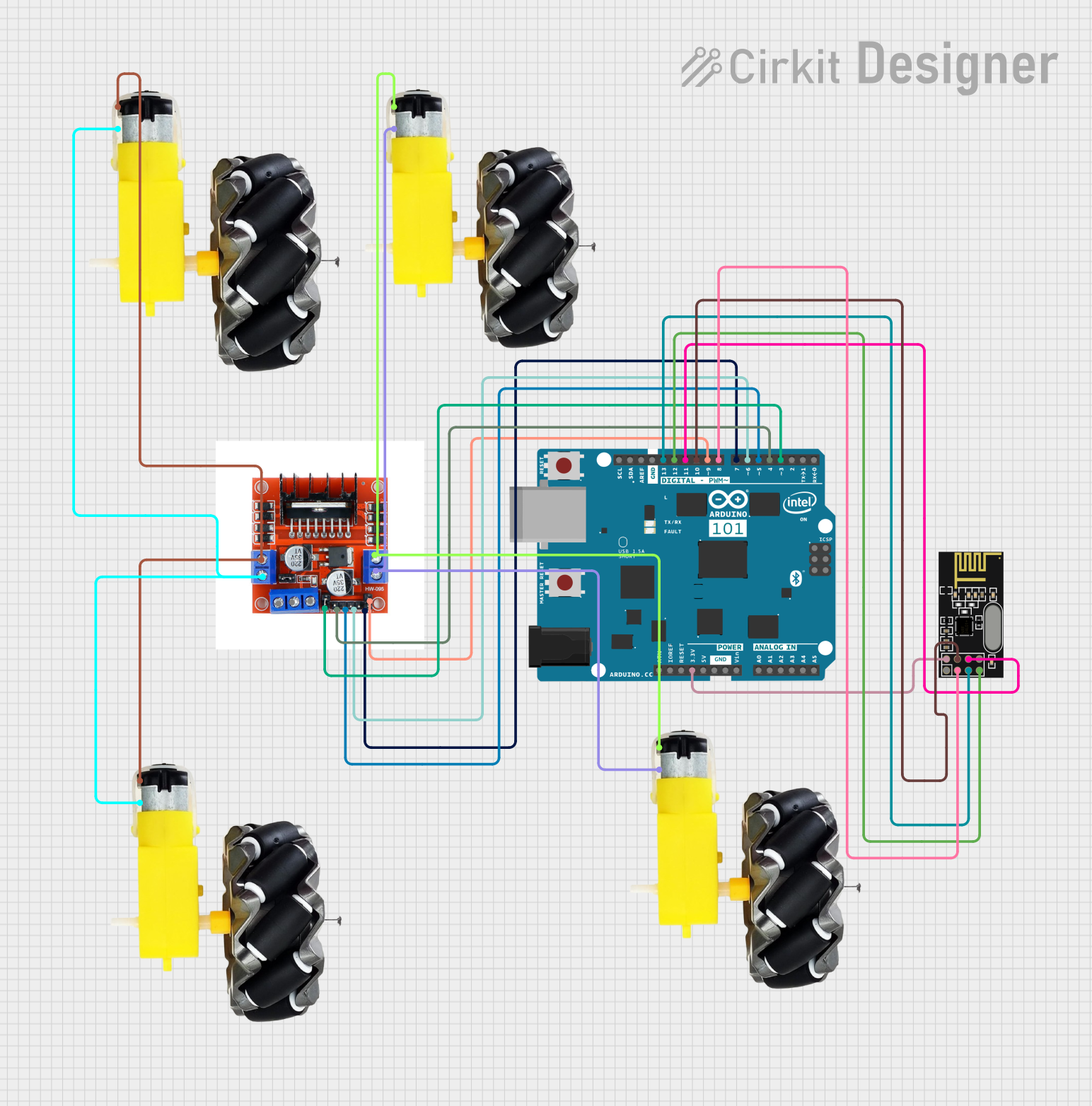
Circuit Documentation
Summary
This document provides a detailed overview of a circuit that includes an Arduino 101 microcontroller, an NRF24L01 wireless module, an L298N motor driver, and multiple motor and wheel assemblies. The circuit is designed to control the motors using the Arduino and communicate wirelessly via the NRF24L01 module.
Component List
Arduino 101
- Description: A microcontroller board based on the Intel Curie module.
- Pins: A5/SCL, A4/SDA, AREF, GND, D13/SCK, D12/MISO, D11 PWM/MOSI, D10 PWM/SS, D9 PWM, D8, D7, D6 PWM, D5 PWM, D4, D3 PWM, D2, D1/TX, D0/RX, AIN, ioref, RESET, 3V3, 5V, VIN, A0, A1, A2, A3, ICSP MISO, ICSP SCK, ICSP MOSI
Motor and Wheels
- Description: A motor and wheel assembly.
- Pins: vcc, GND
NRF24L01
- Description: A wireless transceiver module.
- Pins: IRQ (not used), MOSI, CSN, VCC (3V), GND, CE, SCK, MISO
L298N 2A Dual Motor Driver Module with PWM Control
- Description: A motor driver module capable of controlling two motors with PWM.
- Pins: OUT1, OUT2, 12V, GND, 5V, OUT4, OUT3, ENA, IN1, IN2, IN3, ENB, IN4
Wiring Details
Arduino 101
- D13/SCK connected to NRF24L01 SCK
- D12/MISO connected to NRF24L01 MISO
- D11 PWM/MOSI connected to NRF24L01 MOSI
- D10 PWM/SS connected to NRF24L01 CSN
- D9 PWM connected to L298N ENB
- D8 connected to NRF24L01 CE
- D7 connected to L298N IN4
- D6 PWM connected to L298N IN3
- D5 PWM connected to L298N IN2
- D4 connected to L298N IN1
- D3 PWM connected to L298N ENA
- 3V3 connected to NRF24L01 VCC (3V)
Motor and Wheels
- vcc of one motor connected to L298N OUT4
- GND of the same motor connected to L298N OUT3
- vcc of another motor connected to L298N OUT1
- GND of the same motor connected to L298N OUT2
NRF24L01
- SCK connected to Arduino 101 D13/SCK
- MISO connected to Arduino 101 D12/MISO
- MOSI connected to Arduino 101 D11 PWM/MOSI
- CSN connected to Arduino 101 D10 PWM/SS
- CE connected to Arduino 101 D8
- VCC (3V) connected to Arduino 101 3V3
L298N 2A Dual Motor Driver Module with PWM Control
- ENB connected to Arduino 101 D9 PWM
- IN4 connected to Arduino 101 D7
- IN3 connected to Arduino 101 D6 PWM
- IN2 connected to Arduino 101 D5 PWM
- IN1 connected to Arduino 101 D4
- ENA connected to Arduino 101 D3 PWM
- OUT4 connected to vcc of one motor
- OUT3 connected to GND of the same motor
- OUT1 connected to vcc of another motor
- OUT2 connected to GND of the same motor
Code
No code is provided for this circuit.
This document provides a comprehensive overview of the circuit, including a summary, a detailed component list, wiring details, and a section for code documentation. The wiring details ensure that each component is correctly connected to the Arduino 101 and other components in the circuit.