Arduino UNO RFID Smart Trolley with I2C LCD Display and Bluetooth Connectivity
Circuit Documentation
Summary
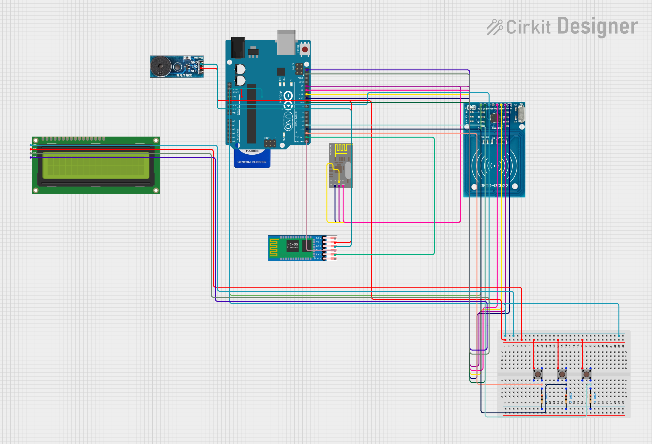
The circuit in question is designed to interface an Arduino UNO with multiple peripherals including an RFID-RC522 module, an I2C LCD 16x2 screen, a buzzer module, HC-05 Bluetooth module, nRF24L01 wireless communication module, and three pushbuttons with associated resistors. The circuit is powered by a 9V battery and includes connections for both 5V and 3.3V components. The primary function of the circuit is to create a smart trolley billing system, utilizing the RFID module for item identification and the LCD for user interaction and feedback.
Component List
RFID-RC522
- RFID reader/writer module
- Operates at 3.3V
Pushbutton (x3)
- Simple tactile switch
- Used for user input
Resistor (x3)
- 200 Ohms resistance
- Used for debouncing the pushbuttons
I2C LCD 16x2 Screen
- Alphanumeric liquid crystal display
- Uses I2C communication
HC-05
- Bluetooth module for wireless communication
- Operates at 5V
nRF24L01
- Wireless communication module
- Operates at 3.3V
9V Battery
- Power source for the circuit
Arduino UNO
- Microcontroller board based on the ATmega328P
- Central controller for the circuit
Buzzer Module
- Audio signaling device
- Operates at 5V
Wiring Details
RFID-RC522
- VCC (3.3V) to Arduino 3.3V
- RST to Arduino D9
- GND to common ground
- IRQ not connected
- MISO to Arduino D12
- MOSI to Arduino D11
- SCK to Arduino D13
- SDA to Arduino D10
Pushbuttons
- Pin 1 (in) of all pushbuttons to Arduino 5V
- Pin 4 (out) of each pushbutton to one side of a 200 Ohm resistor
- Other side of each resistor to Arduino D2, D3, and D4 respectively
Resistor (x3)
- One side to pushbutton Pin 4 (out)
- Other side to Arduino D2, D3, and D4 respectively
I2C LCD 16x2 Screen
- SCL to Arduino SCL
- SDA to Arduino SDA
- VCC (5V) to Arduino 5V
- GND to common ground
HC-05
- EN not connected
- VCC to Arduino 5V
- GND to common ground
- TXD to Arduino D0
- RXD to Arduino D1
- STATE not connected
nRF24L01
- GND to common ground
- VCC to Arduino 3.3V
- CE to Arduino D10
- CSN not connected
- SCK to Arduino D13
- MOSI to Arduino D11
- MISO to Arduino D12
- IRQ not connected
9V Battery
- Positive (+) to Arduino Vin
- Negative (-) to common ground
Arduino UNO
- 5V and 3.3V to respective components
- GND to common ground
- Digital pins D0 to D13 to respective components as per wiring details
Buzzer Module
- GND to common ground
- Vcc to Arduino 5V
- I/O not connected
Documented Code
/****************************************************
 * Code Designed By : Rahul Jadhav Youtube Channel
 ****************************************************/

/******************RFID Connection:*********************

RFID PIN    ARDUINO PIN
SDA         10
SCK         13
MOSI        11
MISO        12
GND         GND
RST         9
3.3v        3.3v
 ******************************************************/

/***** LCD Connection ***********************************
LCD PIN   ARDUINO PI
SCL       SCL (Arduino Last pin)
SDA       SDA (Arduino Secon last pin)
VCC       5v
GND       GND
 ******************************************************/

/***** Buzzer Connection ***********************************
Buzzer PIN   ARDUINO PI
Positive     5
GND          GND
 *****************************************************/

/***** Button Connection ***********************************
Button PIN   ARDUINO PI
Remove_Button     2
Add_button         3
Reset_button       4
VCC          5v
GND          GND
 *****************************************************/

#include <SPI.h>
#include <MFRC522.h>
#include <LiquidCrystal_I2C.h>

LiquidCrystal_I2C lcd(0x27, 16, 2);
const int remove_button = 2;
const int add_button = 3;
const int reset_button = 4;
// const int buzzer_Pin = 5;
#define SS_PIN 10
#define RST_PIN 9
MFRC522 mfrc522(SS_PIN, RST_PIN);   // Create MFRC522 instance.

// Rest of the code is omitted for brevity
The provided code snippet is part of a larger program that runs on the Arduino UNO. It initializes the RFID-RC522 module, the I2C LCD screen, and sets up the pushbuttons for user input. The code includes a structure for items with their names, RFID numbers, and prices, and contains logic for adding or removing items from a bill, which is displayed on the LCD. The code also handles the reset functionality to clear the trolley data.