
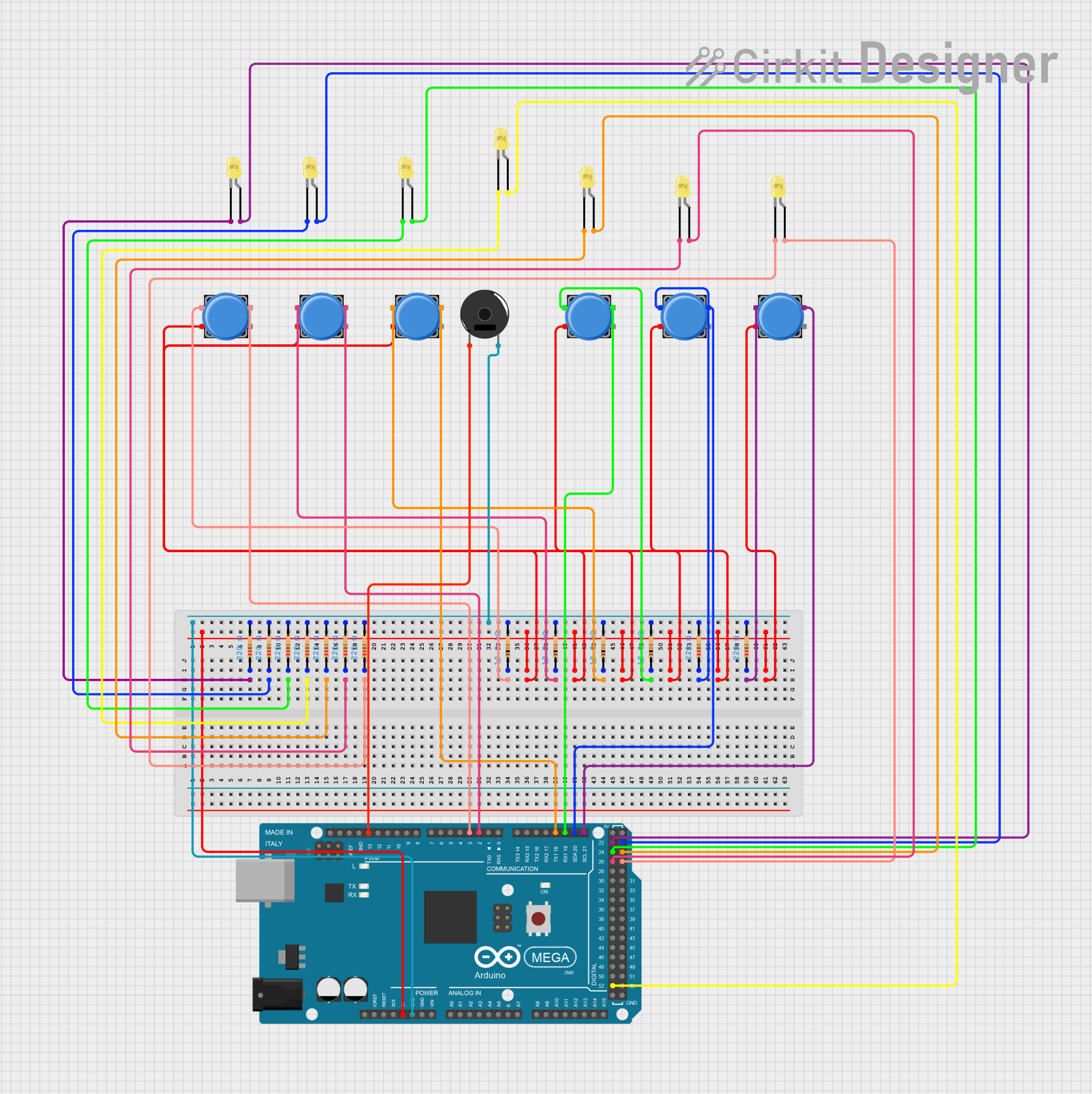
Circuit Documentation
Summary
This circuit is designed to create an interactive game using an Arduino Mega 2560 microcontroller. The game involves pressing buttons in response to LED lights, with a piezo buzzer providing audio feedback. The circuit includes multiple LEDs, resistors, pushbuttons, and a piezo buzzer, all connected to the Arduino Mega 2560.
Component List
Arduino Mega 2560
- Description: Microcontroller board based on the ATmega2560.
- Pins: IOREF, RESET, 3V3, 5V, GND, VIN, A0-A15, D0-D53, AREF, SDA, SCL
Resistors
- Description: Various resistors used for current limiting and pull-down purposes.
- Pins: pin1, pin2
- Properties:
- Resistance: 220 Ohms
- Resistance: 10,000 Ohms
Pushbuttons
- Description: Mechanical switches used for user input.
- Pins: Pin 1, Pin 2, Pin 3, Pin 4
LED: Two Pin (yellow)
- Description: Yellow LEDs used for visual feedback.
- Pins: cathode, anode
Piezo Buzzer
- Description: Buzzer used for audio feedback.
- Pins: pin 1, pin 2
Wiring Details
Arduino Mega 2560
- 5V: Connected to Pin 1 of all pushbuttons.
- GND: Connected to pin2 of all resistors and pin 2 of the piezo buzzer.
- D21/SCL: Connected to Pin 4 of a pushbutton.
- D20/SDA: Connected to Pin 4 of a pushbutton.
- D19/RX1: Connected to Pin 4 of a pushbutton.
- D18/TX1: Connected to Pin 4 of a pushbutton.
- D2 PWM: Connected to Pin 4 of a pushbutton.
- D3 PWM: Connected to Pin 4 of a pushbutton.
- D13 PWM: Connected to pin 1 of the piezo buzzer.
- D52: Connected to the anode of an LED.
- D26: Connected to the anode of an LED.
- D24: Connected to the anode of an LED.
- D22: Connected to the anode of an LED.
- D27: Connected to the anode of an LED.
- D25: Connected to the anode of an LED.
- D23: Connected to the anode of an LED.
Resistors
220 Ohms Resistors:
- pin1: Connected to the cathode of an LED.
- pin2: Connected to GND.
10,000 Ohms Resistors:
- pin1: Connected to Pin 3 of a pushbutton.
- pin2: Connected to GND.
Pushbuttons
- Pin 1: Connected to 5V.
- Pin 3: Connected to pin1 of a 10,000 Ohms resistor.
- Pin 4: Connected to various digital pins on the Arduino Mega 2560.
LEDs
- cathode: Connected to pin1 of a 220 Ohms resistor.
- anode: Connected to various digital pins on the Arduino Mega 2560.
Piezo Buzzer
- pin 1: Connected to D13 PWM on the Arduino Mega 2560.
- pin 2: Connected to GND.
Code Documentation
sketch.ino
void setup() {
    #include "pitches.h" // Allowing the Arduino to output music from a buzzer

    int wacks = 0; // How many time someone successfully "wacks" the buttons on time
    int gameActive = 1; // This makes it so you can only play the game when the light show is not going on
    int level = 1; //The amount of times you got to 8 "wacks"
    int speed = 1000; // The delay in between lights
    volatile long last_micros = 0; // Volatile because it's used in ISRs

    const int shamash = 52; // Whenever "shamash" is said, it means the digital pin 52
    const int light6 = 22; // Whenever "light6" is said, it means the digital pin 22
    const int light5 = 23; // Whenever "light5" is said, it means the digital pin 23
    const int light4 = 24; // Whenever "light4" is said, it means the digital pin 24
    const int light3 = 25; //Whenever "light3" is said, it means the digital pin 25
    const int light2 = 26; //Whenever "light2" is said, it means the digital pin 26
    const int light1 = 27; //Whenever "light1" is said, it means the digital pin 27

    const int button1 = 3; //Whenever "button1" is hit, it means the interrupt of pin 3
    const int button2 = 2; //Whenever "button2" is hit, it means the interrupt of pin 2
    const int button3 = 18; //Whenever "button3" is hit, it means the interrupt of pin 18
    const int button4 = 19; //Whenever "button4" is hit, it means the interrupt of pin 19
    const int button5 = 20; //Whenever "button5" is hit, it means the interrupt of pin 20
    const int button6 = 21; //Whenever "button6" is hit, it means the interrupt of pin 21

    // notes in the melody:
    int melody[] = { //defining 'melody' as:
        NOTE_E4, NOTE_B3, NOTE_E4, NOTE_A4, NOTE_GS4, NOTE_FS4, NOTE_E4, NOTE_B4, NOTE_CS5, NOTE_FS4, NOTE_GS4, NOTE_A4, NOTE_GS4, NOTE_FS4, NOTE_E4 //the array of notes that will play 'Maoz Tzur'
    };

    // note durations: how long each note will last 4 = a quarter note, 8 = a eighth note, and 2 = a half note
    int noteDurations[] = { //defining the duration of the notes and the array of noteDurations
        4, 4, 4, 4, 4, 4, 2, 4, 4, 4, 8, 8, 4, 4, 4 // how long each note will play for (full notes, half notes, and fourth notes)
    };

    Serial.begin(9600); // Opening the serial monitor

    //declares the LEDs as outputs
    pinMode(shamash, OUTPUT); // Declaring "shamash" as an output
    pinMode(light1, OUTPUT); // Declaring "light1" as an output
    pinMode(light2, OUTPUT); // Declaring "light2" as an output
    pinMode(light3, OUTPUT); // Declaring "light3" as an output
    pinMode(light4, OUTPUT); // Declaring "light4" as an output
    pinMode(light5, OUTPUT); // Declaring "light5" as an output
    pinMode(light6, OUTPUT); // Declaring "light6" as an output

    //declares buttons as inputs
    pinMode(button1, INPUT); // Declaring "button1" as an input
    pinMode(button2, INPUT); // Declaring "button2" as an input
    pinMode(button3, INPUT); // Declaring "button3" as an input
    pinMode(button4, INPUT); // Declaring "button4" as an input
    pinMode(button5, INPUT); // Declaring "button5" as an input
    pinMode(button6, INPUT); // Declaring "button6" as an input

    //sets up interrupts
    attachInterrupt(digitalPinToInterrupt(button1), button1Pressed, RISING); // adding an interrupt to "button1", connected to the function 'button1Pressed', and the ISR is triggered when the pin goes from high to low
    attachInterrupt(digitalPinToInterrupt(button2), button2Pressed, RISING); // adding an interrupt to "button2", connected to the function 'button2Pressed', and the ISR is triggered when the pin goes from high to low
    attachInterrupt(digitalPinToInterrupt(button3), button3Pressed, RISING); // adding an interrupt to "button3", connected to the function 'button3Pressed', and the ISR is triggered when the pin goes from high to low
    attachInterrupt(digitalPinToInterrupt(button4), button4Pressed, RISING); // adding an interrupt to "button4", connected to the function 'button4Pressed', and the ISR is triggered when