
Circuit Documentation
Summary of the Circuit
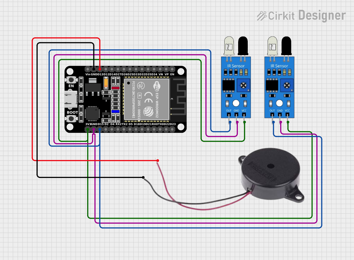
The circuit in question appears to be designed for sensing infrared (IR) signals and providing an audible alert through a buzzer. It is based on the ESP32 microcontroller, which is a versatile and powerful chip with Wi-Fi and Bluetooth capabilities, although these features are not explicitly utilized in the current configuration. The circuit includes two IR sensors that likely detect some form of IR signal, and a buzzer that is controlled by the ESP32 to emit sound based on the IR sensors' outputs.
Component List
ESP32 (30 pin)
- Description: A 30-pin microcontroller with a variety of digital and analog I/O pins.
- Purpose: Acts as the central processing unit of the circuit, reading IR sensor outputs and driving the buzzer.
IR Sensor
- Description: An infrared sensor with an output pin that goes high when IR light is detected.
- Purpose: To detect infrared signals and send the detection output to the ESP32.
Buzzer
- Description: An electromechanical component that emits sound when powered.
- Purpose: To provide an audible alert when an IR signal is detected by the sensors.
Wiring Details
ESP32 (30 pin)
- D13: Connected to the positive pin of the Buzzer.
- GND: Common ground connection with the Buzzer and both IR sensors.
- D15: Connected to the output pins of both IR sensors.
- 3V3: Powers both IR sensors by providing a 3.3V supply.
IR Sensor 1
- out: Connected to the D15 pin on the ESP32.
- gnd: Connected to the ground (GND) on the ESP32.
- vcc: Connected to the 3.3V (3V3) supply from the ESP32.
IR Sensor 2
- out: Connected to the D15 pin on the ESP32.
- gnd: Connected to the ground (GND) on the ESP32.
- vcc: Connected to the 3.3V (3V3) supply from the ESP32.
Buzzer
- POSITIVE: Connected to the D13 pin on the ESP32.
- NEGATIVE: Connected to the ground (GND) on the ESP32.
Documented Code
No code has been provided for the microcontroller. To fully utilize this circuit, embedded code for the ESP32 is required to read the state of the IR sensors and control the buzzer accordingly. The code would typically include initialization of the GPIO pins, a main loop to read the sensor states, and logic to activate the buzzer when an IR signal is detected.