
Circuit Documentation
Summary
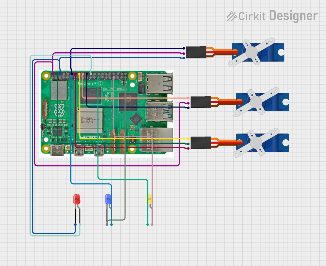
This document provides a detailed overview of a circuit involving a Raspberry Pi 5, three Tower Pro SG90 servos, and three LEDs (red, blue, and yellow). The Raspberry Pi 5 serves as the central control unit, interfacing with the servos and LEDs through its GPIO pins. The servos are powered by the 5V supply from the Raspberry Pi, and the LEDs are connected to various GPIO pins for control.
Component List
Raspberry Pi 5
- Description: A single-board computer used as the central control unit.
- Pins: Type-C, Micro HDMI 1, Micro HDMI 2, Camera 1, Camera 2, PoE, Fan, PCIe, USB 3.0, USB 2.0, Ethernet, 5V, GND, 3.3v, GPIO 14, GPIO 15, GPIO 18, GPIO 23, GPIO 24, GPIO 25, GPIO 8, GPIO 7, GPIO 1, GPIO 12, GPIO 16, GPIO 20, GPIO 21, GPIO 2, GPIO 3, GPIO 4, GPIO 17, GPIO 27, GPIO 22, GPIO 10, GPIO 9, GPIO 11, GPIO 0, GPIO 5, GPIO 6, GPIO 13, GPIO 19, GPIO 26
Tower Pro SG90 Servo (3 units)
- Description: A small servo motor used for precise control of angular position.
- Pins: Signal, +5V, GND
LED: Two Pin (Red)
- Description: A red LED used for visual indication.
- Pins: Cathode, Anode
LED: Two Pin (Blue)
- Description: A blue LED used for visual indication.
- Pins: Cathode, Anode
LED: Two Pin (Yellow)
- Description: A yellow LED used for visual indication.
- Pins: Cathode, Anode
Wiring Details
Raspberry Pi 5
5V Pin:
- Connected to +5V pin of all three Tower Pro SG90 servos.
GND Pin:
- Connected to GND pin of all three Tower Pro SG90 servos.
- Connected to the cathode of the red LED.
- Connected to the cathode of the blue LED.
- Connected to the cathode of the yellow LED.
GPIO 18:
- Connected to the Signal pin of the first Tower Pro SG90 servo.
GPIO 23:
- Connected to the Signal pin of the third Tower Pro SG90 servo.
GPIO 24:
- Connected to the Signal pin of the second Tower Pro SG90 servo.
GPIO 25:
- Connected to the anode of the red LED.
GPIO 17:
- Connected to the anode of the blue LED.
GPIO 13:
- Connected to the anode of the yellow LED.
Tower Pro SG90 Servo (1st Unit)
Signal Pin:
- Connected to GPIO 18 of the Raspberry Pi 5.
+5V Pin:
- Connected to 5V pin of the Raspberry Pi 5.
GND Pin:
- Connected to GND pin of the Raspberry Pi 5.
Tower Pro SG90 Servo (2nd Unit)
Signal Pin:
- Connected to GPIO 24 of the Raspberry Pi 5.
+5V Pin:
- Connected to 5V pin of the Raspberry Pi 5.
GND Pin:
- Connected to GND pin of the Raspberry Pi 5.
Tower Pro SG90 Servo (3rd Unit)
Signal Pin:
- Connected to GPIO 23 of the Raspberry Pi 5.
+5V Pin:
- Connected to 5V pin of the Raspberry Pi 5.
GND Pin:
- Connected to GND pin of the Raspberry Pi 5.
LED: Two Pin (Red)
Cathode:
- Connected to GND pin of the Raspberry Pi 5.
Anode:
- Connected to GPIO 25 of the Raspberry Pi 5.
LED: Two Pin (Blue)
Cathode:
- Connected to GND pin of the Raspberry Pi 5.
Anode:
- Connected to GPIO 17 of the Raspberry Pi 5.
LED: Two Pin (Yellow)
Cathode:
- Connected to GND pin of the Raspberry Pi 5.
Anode:
- Connected to GPIO 13 of the Raspberry Pi 5.
Code
No code is provided for this circuit.