
Circuit Documentation
Summary of the Circuit
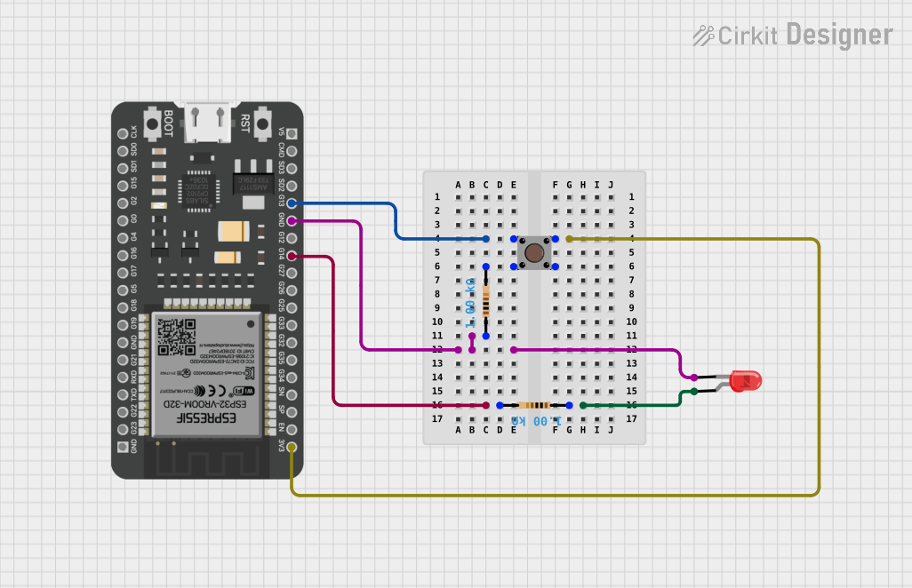
This circuit appears to be a simple user input and output system that utilizes an ESP32 microcontroller. The circuit includes a pushbutton that, when pressed, likely triggers an input to the ESP32. There is also a red LED that is presumably used as an output indicator. The LED is connected through resistors, which are used to limit the current to the LED to prevent damage. Since no code is provided, the exact behavior of the microcontroller in response to the button press is not specified.
Component List
LED: Two Pin (red)
- Description: A red light-emitting diode (LED) with two pins: anode and cathode.
- Purpose: Typically used as an output indicator in circuits.
Pushbutton
- Description: A momentary pushbutton with four pins: two input pins and two output pins.
- Purpose: Acts as a user input device to trigger events in the circuit.
ESP32 - 38 pins
- Description: A microcontroller with WiFi and Bluetooth capabilities and a variety of GPIO pins.
- Purpose: Acts as the central processing unit of the circuit, controlling the behavior of the inputs and outputs.
Resistor (1 kOhms)
- Description: A resistor with a resistance of 1000 Ohms.
- Purpose: Used to limit the current flowing through the LED and protect the ESP32 GPIO pins from high current.
Wiring Details
LED: Two Pin (red)
- Cathode: Connected to a 1 kOhm resistor, which is then connected to the GND pin of the ESP32.
- Anode: Connected to another 1 kOhm resistor, which is then connected to GPIO 14 (G14) of the ESP32.
Pushbutton
- Pin 1 (in): Connected to the 3V3 pin of the ESP32, providing power to the button.
- Pin 2 (in): Connected to GPIO 13 (G13) of the ESP32, likely used to detect button presses.
- Pin 3 (out): Not connected in the provided net list.
- Pin 4 (out): Connected to one end of a 1 kOhm resistor, the other end of which is connected to the cathode of the LED.
ESP32 - 38 pins
- 3V3: Provides power to the pushbutton.
- GND: Connected to the cathode of the LED through a 1 kOhm resistor.
- G13: Connected to Pin 2 (in) of the pushbutton, used to detect button presses.
- G14: Connected to the anode of the LED through a 1 kOhm resistor, likely used to control the LED.
Resistor (1 kOhms)
- First Resistor: One end connected to the cathode of the LED and the other end to the GND pin of the ESP32.
- Second Resistor: One end connected to the anode of the LED and the other end to GPIO 14 (G14) of the ESP32.
Documented Code
No code has been provided for the microcontroller in this circuit. Therefore, there is no code to document at this time. When code is available, it should be included here with appropriate comments and explanations of its functionality.