
Wi-Fi Controlled RGB LED Strip with Wemos D1 Mini and Logic Level Converter
View and Edit Project In Cirkit Designer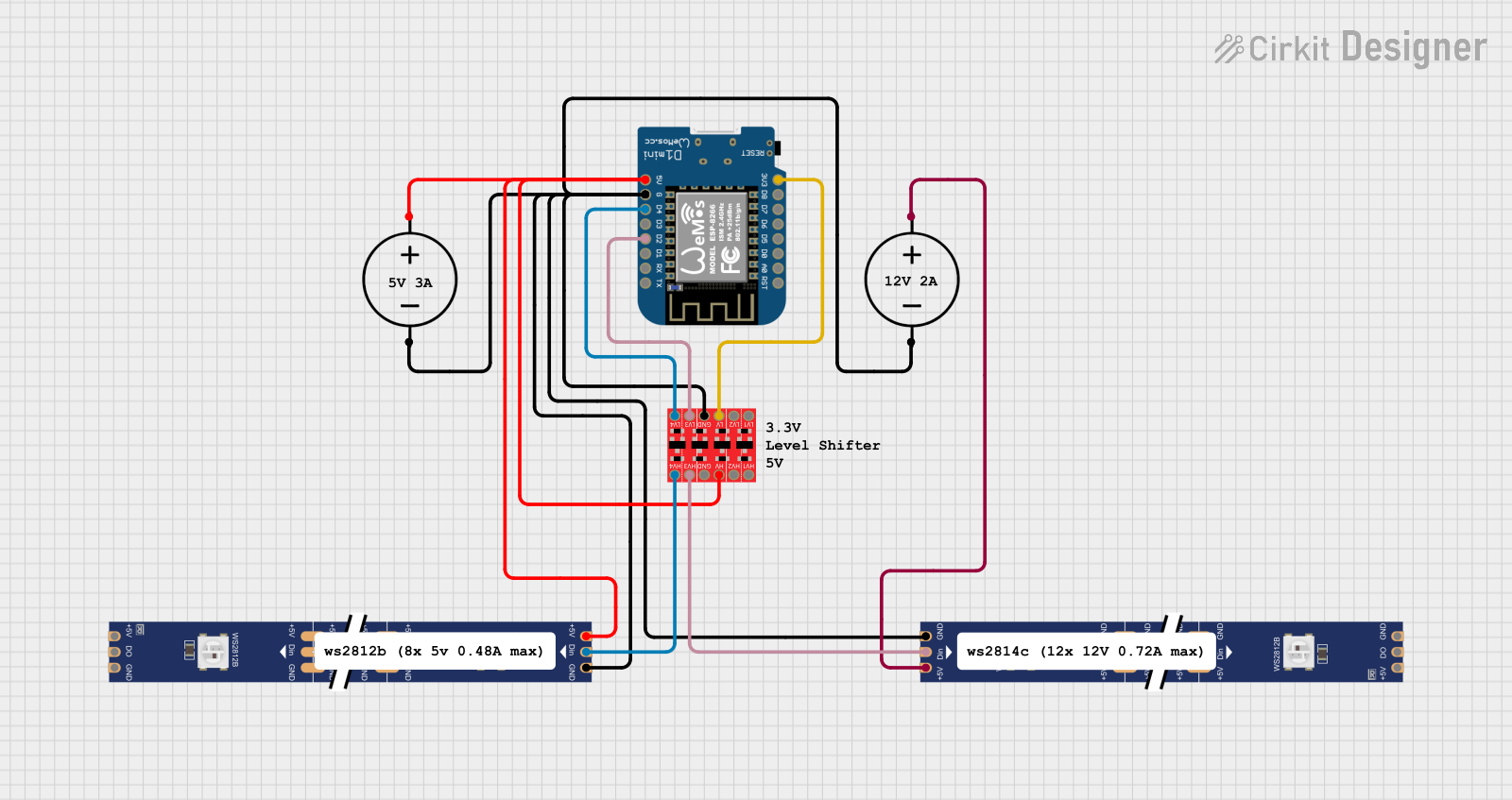
Circuit Documentation
Summary
This document provides a detailed overview of a circuit that includes a Wemos D1 Mini microcontroller, two WS2812 RGB LED strips, a Bi-Directional Logic Level Converter, and two DC Power Sources. The circuit is designed to control the LED strips using the Wemos D1 Mini, with appropriate voltage level shifting provided by the logic level converter.
Component List
Bi-Directional Logic Level Converter
- Description: Converts voltage levels between high voltage (HV) and low voltage (LV) domains.
- Pins: HV1, HV2, HV, GND, HV3, HV4, LV1, LV2, LV, LV3, LV4
DC Power Source
- Description: Provides DC power to the circuit.
- Pins: Ground, Positive
Wemos D1 Mini
- Description: A microcontroller board based on the ESP8266, used for controlling the LED strips.
- Pins: RST, A0, D0, D5, D6, D7, D8, 3V3, 5V, G, D4, D3, D2, D1, RX, TX
WS2812 RGB LED strip
- Description: Individually addressable RGB LED strip.
- Pins: DIN, 5V, GND, DO
Wiring Details
Bi-Directional Logic Level Converter
- HV Pin: Connected to the Positive pin of the DC Power Source and the 5V pin of the Wemos D1 Mini.
- GND Pin: Connected to the Ground pin of the DC Power Source, the G pin of the Wemos D1 Mini, and the GND pins of both WS2812 RGB LED strips.
- HV3 Pin: Connected to the DIN pin of the second WS2812 RGB LED strip.
- HV4 Pin: Connected to the DIN pin of the first WS2812 RGB LED strip.
- LV Pin: Connected to the 3V3 pin of the Wemos D1 Mini.
- LV3 Pin: Connected to the D2 pin of the Wemos D1 Mini.
- LV4 Pin: Connected to the D4 pin of the Wemos D1 Mini.
DC Power Source 1
- Positive Pin: Connected to the 5V pin of the first WS2812 RGB LED strip and the HV pin of the Bi-Directional Logic Level Converter.
- Ground Pin: Connected to the GND pin of the first WS2812 RGB LED strip, the G pin of the Wemos D1 Mini, the Ground pin of the second DC Power Source, and the GND pin of the Bi-Directional Logic Level Converter.
DC Power Source 2
- Positive Pin: Connected to the 5V pin of the second WS2812 RGB LED strip.
- Ground Pin: Connected to the Ground pin of the first DC Power Source.
Wemos D1 Mini
- 5V Pin: Connected to the Positive pin of the first DC Power Source and the HV pin of the Bi-Directional Logic Level Converter.
- 3V3 Pin: Connected to the LV pin of the Bi-Directional Logic Level Converter.
- G Pin: Connected to the Ground pin of the first DC Power Source, the GND pins of both WS2812 RGB LED strips, and the GND pin of the Bi-Directional Logic Level Converter.
- D2 Pin: Connected to the LV3 pin of the Bi-Directional Logic Level Converter.
- D4 Pin: Connected to the LV4 pin of the Bi-Directional Logic Level Converter.
WS2812 RGB LED strip 1
- 5V Pin: Connected to the Positive pin of the first DC Power Source.
- GND Pin: Connected to the Ground pin of the first DC Power Source, the G pin of the Wemos D1 Mini, and the GND pin of the Bi-Directional Logic Level Converter.
- DIN Pin: Connected to the HV4 pin of the Bi-Directional Logic Level Converter.
WS2812 RGB LED strip 2
- 5V Pin: Connected to the Positive pin of the second DC Power Source.
- GND Pin: Connected to the Ground pin of the first DC Power Source, the G pin of the Wemos D1 Mini, and the GND pin of the Bi-Directional Logic Level Converter.
- DIN Pin: Connected to the HV3 pin of the Bi-Directional Logic Level Converter.
Code
No code is provided for this circuit.
This document provides a comprehensive overview of the circuit, including a summary, component list, wiring details, and code documentation. The wiring details section ensures that each component's connections are clearly described, facilitating easy assembly and troubleshooting.