
Arduino and ESP32 Controlled Smart Humidifier and UV-C LED System with Fan Automation
View and Edit Project In Cirkit Designer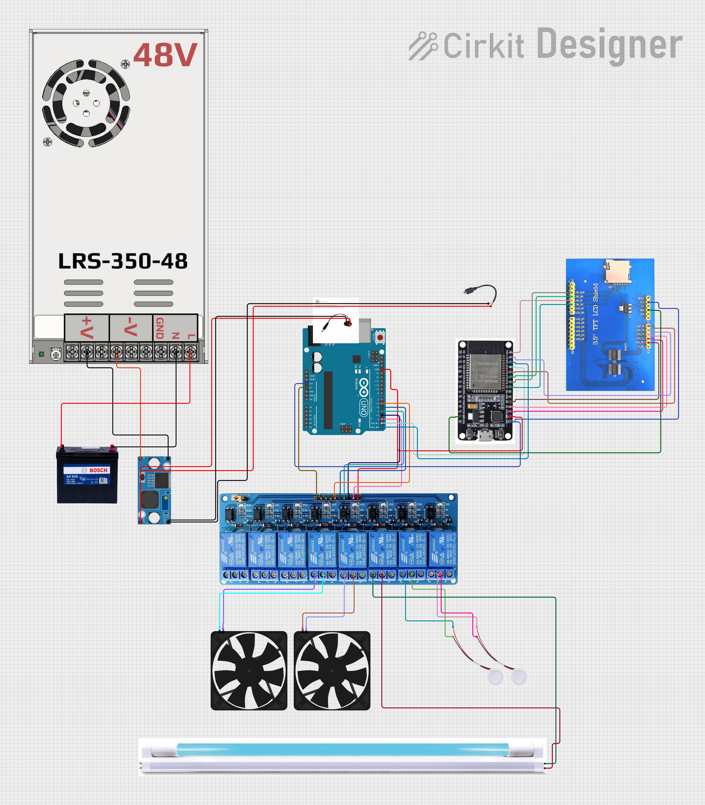
Circuit Documentation
Summary
This circuit is designed to control a humidifier, UV-C LED, and fans using an Arduino UNO and an ESP32 microcontroller. The Arduino UNO is responsible for controlling a 5V 8-channel relay module, which in turn powers the humidifier, UV-C LED, and fans in a specific sequence. The ESP32 is used to interface with a 3.5" TFT LCD Shield for display purposes. Power is supplied by a 12V 200Ah battery and regulated using an LM2596 step-down module.
Component List
Fan
- Pins: GND, 5V
- Description: A fan used for ventilation.
Humidifier
- Pins: GND, 5V
- Description: A device used to add moisture to the air.
5V 8-Channel Relay
- Pins: GND, IN1, IN2, IN3, IN4, IN5, IN6, IN7, IN8, VCC, NC, C, NO
- Description: A relay module used to control multiple devices.
UV-C LED
- Pins: +, -
- Description: A UV-C LED used for sterilization.
LM2596 Step Down Module
- Pins: OUT-, OUT+, IN-, IN+
- Description: A step-down voltage regulator.
ESP32
- Pins: EN, VP, VN, D34, D35, D32, D33, D25, D26, D27, D14, D12, D13, GND, VIN, 3V3, D15, D2, D4, RX2, TX2, D5, D18, D19, D21, RX0, TX0, D22, D23, BOOT
- Description: A microcontroller with Wi-Fi and Bluetooth capabilities.
3.5" TFT LCD Shield (320 x 480)
- Pins: SD_SCK, SD_DO, SD_DI, SD_SS, LCD_D1, LCD_D0, LCD_D7, LCD_D6, LCD_D5, LCD_D4, LCD_D3, LCD_D2, F_CS, LCD_RST, LCD_CS, LCD_RS, LCD_WR, LCD_RD, GND, 5V, 3.3V, RESET
- Description: A display shield for visual output.
MW LRS-350-48
- Pins: +48V output, -48V output, GND, N, L
- Description: A power supply unit.
12V 200Ah Battery
- Pins: GND, 12V
- Description: A battery for power supply.
Arduino UNO
- Pins: UNUSED, IOREF, Reset, 3.3V, 5V, GND, Vin, A0, A1, A2, A3, A4, A5, SCL, SDA, AREF, D13, D12, D11, D10, D9, D8, D7, D6, D5, D4, D3, D2, D1, D0
- Description: A microcontroller board based on the ATmega328P.
Power Jack
- Pins: vcc, gnd
- Description: A power jack for connecting external power.
Micro USB to Cable (2 Pin)
- Pins: Micro USB, +, -
- Description: A cable for connecting micro USB to other components.
Wiring Details
Fan
- GND connected to 5V 8-Channel Relay (C)
- 5V connected to 5V 8-Channel Relay (NO)
Humidifier
- GND connected to 5V 8-Channel Relay (C)
- 5V connected to 5V 8-Channel Relay (NO)
5V 8-Channel Relay
- GND connected to Arduino UNO (GND) and ESP32 (GND)
- IN1 connected to Arduino UNO (D2)
- IN2 connected to Arduino UNO (D3)
- IN3 connected to Arduino UNO (D4)
- IN4 connected to Arduino UNO (D5)
- IN5 connected to Arduino UNO (D6)
- VCC connected to Arduino UNO (5V)
- C connected to Humidifier (GND), UV-C LED (-), Fan (GND)
- NO connected to Humidifier (5V), UV-C LED (+), Fan (5V)
UV-C LED
- - connected to 5V 8-Channel Relay (C)
- + connected to 5V 8-Channel Relay (NO)
LM2596 Step Down Module
- OUT- connected to Power Jack (gnd) and Micro USB to Cable (2 Pin) (-)
- OUT+ connected to Power Jack (vcc) and Micro USB to Cable (2 Pin) (+)
- IN- connected to MW LRS-350-48 (-48V output)
- IN+ connected to MW LRS-350-48 (+48V output)
ESP32
- GND connected to Arduino UNO (GND) and 3.5" TFT LCD Shield (GND)
- 3V3 connected to Arduino UNO (3.3V) and 3.5" TFT LCD Shield (3.3V)
- RX0 connected to Arduino UNO (D1)
- TX0 connected to Arduino UNO (D0)
- D15 connected to 3.5" TFT LCD Shield (LCD_CS)
- D2 connected to 3.5" TFT LCD Shield (LCD_RS)
- D4 connected to 3.5" TFT LCD Shield (LCD_RST)
- D5 connected to 3.5" TFT LCD Shield (SD_SS)
- D18 connected to 3.5" TFT LCD Shield (SD_SCK)
- D19 connected to 3.5" TFT LCD Shield (SD_DO)
- D21 connected to 3.5" TFT LCD Shield (LCD_RD)
- D22 connected to 3.5" TFT LCD Shield (LCD_WR)
- D23 connected to 3.5" TFT LCD Shield (SD_DI)
3.5" TFT LCD Shield (320 x 480)
- 3.3V connected to Arduino UNO (3.3V) and ESP32 (3V3)
- GND connected to ESP32 (GND)
- LCD_CS connected to ESP32 (D15)
- LCD_RS connected to ESP32 (D2)
- LCD_RST connected to ESP32 (D4)
- SD_SS connected to ESP32 (D5)
- SD_SCK connected to ESP32 (D18)
- SD_DO connected to ESP32 (D19)
- LCD_RD connected to ESP32 (D21)
- LCD_WR connected to ESP32 (D22)
- SD_DI connected to ESP32 (D23)
MW LRS-350-48
- L connected to 12V 200Ah Battery (GND)
- N connected to 12V 200Ah Battery (12V)
- -48V output connected to LM2596 Step Down Module (IN-)
- +48V output connected to LM2596 Step Down Module (IN+)
12V 200Ah Battery
- GND connected to MW LRS-350-48 (L)
- 12V connected to MW LRS-350-48 (N)
Arduino UNO
- GND connected to 5V 8-Channel Relay (GND) and ESP32 (GND)
- D2 connected to 5V 8-Channel Relay (IN1)
- D3 connected to 5V 8-Channel Relay (IN2)
- D4 connected to 5V 8-Channel Relay (IN3)
- D5 connected to 5V 8-Channel Relay (IN4)
- D6 connected to 5V 8-Channel Relay (IN5)
- 5V connected to 5V 8-Channel Relay (VCC)
- 3.3V connected to ESP32 (3V3) and 3.5" TFT LCD Shield (3.3V)
- D1 connected to ESP32 (RX0)