
Arduino Nano-Controlled AC Bulb Switching System with Keypad Input and LCD Interface
View and Edit Project In Cirkit Designer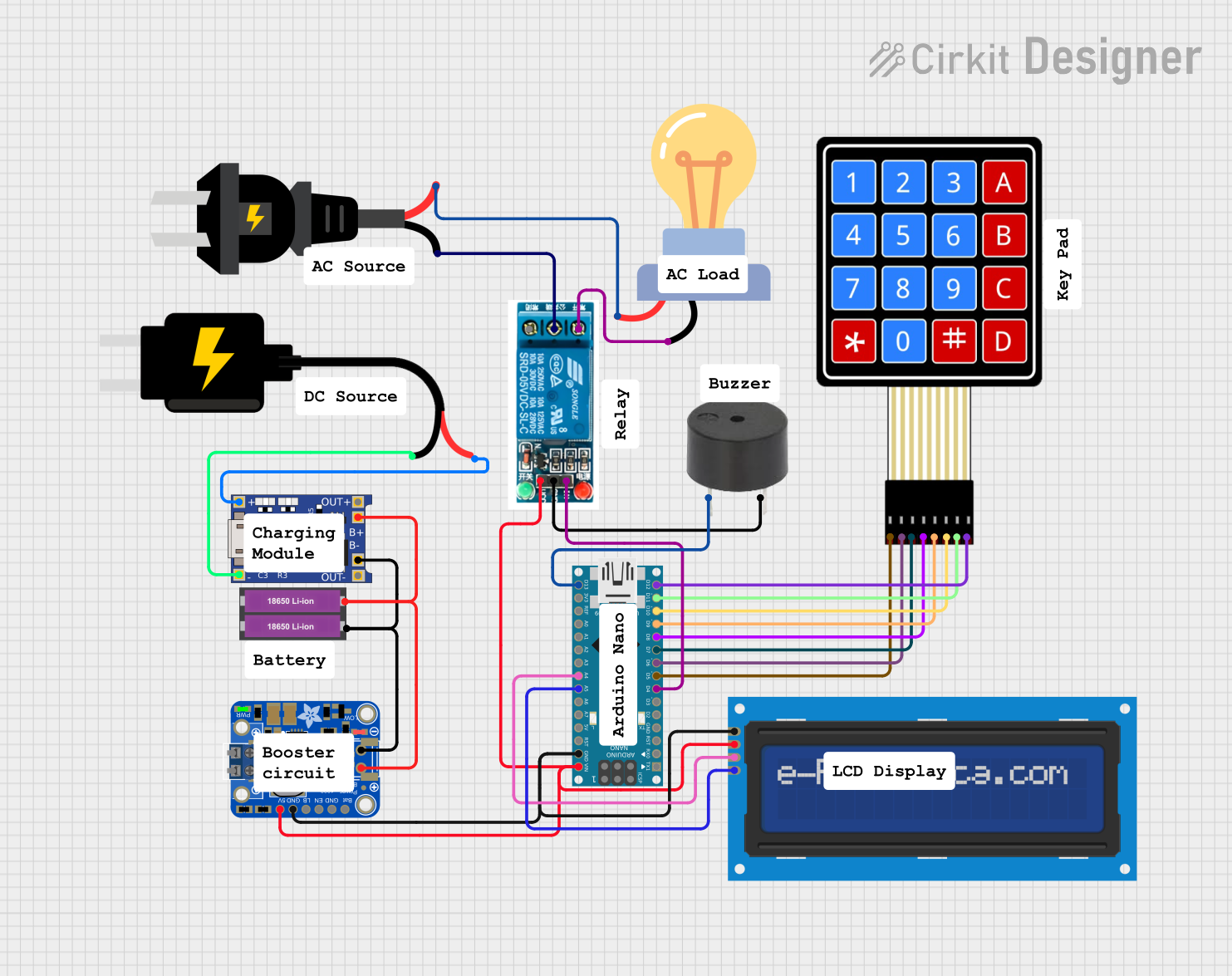
Circuit Documentation
Summary
This document provides a detailed overview of a circuit designed to interface an Arduino Nano with various components including an LCD screen, a relay, a keypad, a buzzer, and power management modules. The circuit is powered by a 5V DC source and includes a charging and power-boosting solution for a Li-ion battery setup. The Arduino Nano serves as the central microcontroller, facilitating user input through a keypad and providing output to an LCD screen and a buzzer. Additionally, the circuit can control an AC-powered LED bulb via a relay.
Component List
LCD Screen 16x2 I2C
- Description: A 16x2 character LCD display with an I2C interface.
- Pins: SCL, SDA, VCC, GND
5V Relay
- Description: A relay module capable of switching AC/DC loads.
- Pins: Normally Open, Common terminal, Normally Closed, In, GND, VCC
4X4 Membrane Matrix Keypad
- Description: A 4x4 matrix keypad for user input.
- Pins: R1, R2, R3, R4, C1, C2, C3, C4
18650 Li-ion Battery x 2
- Description: A pair of 18650 Li-ion batteries for power storage.
- Pins: +, -
DC Source 5V
- Description: A 5V DC power supply.
- Pins: VCC, GND
LED Bulb AC / Bombillo AC
- Description: An AC-powered LED bulb.
- Pins: +, -
AC Source
- Description: An alternating current power source.
- Pins: -, +
Buzzer
- Description: An audible signaling device.
- Pins: PIN, GND
Arduino Nano
- Description: A compact microcontroller board based on the ATmega328.
- Pins: D1/TX, D0/RX, RESET, GND, D2, D3, D4, D5, D6, D7, D8, D9, D10, D11/MOSI, D12/MISO, VIN, 5V, A7, A6, A5, A4, A3, A2, A1, A0, AREF, 3V3, D13/SCK
PowerBoost 1000 Basic Pad Terminal
- Description: A power regulator and booster for Li-ion batteries.
- Pins: VBAT, GND, ENABLE, LBO, 5.0V
TP4056
- Description: A lithium battery charger and protection module.
- Pins: OUT-, B-, B+, OUT+, IN-, IN+
Wiring Details
LCD Screen 16x2 I2C
- SCL connected to Arduino Nano A5
- SDA connected to Arduino Nano A4
- VCC connected to PowerBoost 1000 Basic Pad Terminal 5.0V
- GND connected to PowerBoost 1000 Basic Pad Terminal GND
5V Relay
- Normally Open connected to LED Bulb AC -
- Common terminal connected to AC Source +
- Normally Closed not used in this circuit
- In connected to Arduino Nano D4
- GND connected to PowerBoost 1000 Basic Pad Terminal GND
- VCC connected to PowerBoost 1000 Basic Pad Terminal 5.0V
4X4 Membrane Matrix Keypad
- R1 connected to Arduino Nano D5
- R2 connected to Arduino Nano D6
- R3 connected to Arduino Nano D7
- R4 connected to Arduino Nano D8
- C1 connected to Arduino Nano D9
- C2 connected to Arduino Nano D10
- C3 connected to Arduino Nano D11/MOSI
- C4 connected to Arduino Nano D12/MISO
18650 Li-ion Battery x 2
-
- connected to PowerBoost 1000 Basic Pad Terminal VBAT and TP4056 B+
-
- connected to PowerBoost 1000 Basic Pad Terminal GND and TP4056 B-
DC Source 5V
- VCC connected to TP4056 IN+
- GND connected to TP4056 IN-
LED Bulb AC / Bombillo AC
-
- connected to 5V Relay Normally Open
-
- connected to AC Source -
Buzzer
- PIN connected to Arduino Nano D13/SCK
- GND connected to PowerBoost 1000 Basic Pad Terminal GND
Documented Code
Arduino Nano Code (sketch.ino)
void setup() {
  // put your setup code here, to run once:

}

void loop() {
  // put your main code here, to run repeatedly:

}
Additional Notes
- The provided code is a template and does not include specific functionality. It needs to be populated with the logic to handle keypad inputs, drive the LCD display, control the relay, and activate the buzzer.
- The Arduino Nano's pins are used for I2C communication with the LCD, digital control of the relay, and interfacing with the keypad. The buzzer is also connected to a digital pin for audible output.
- The PowerBoost 1000 Basic Pad Terminal and TP4056 are used for managing the power from the Li-ion batteries, ensuring a stable 5V supply to the circuit components.
- The relay module is used to switch the AC-powered LED bulb on and off, demonstrating the capability of the circuit to control high-power devices.