Arduino UNO Traffic Light Controller
Traffic Light Control Circuit Documentation
Summary
This document describes a simple traffic light control circuit, which is designed to simulate a traffic light system using an Arduino UNO microcontroller and a custom traffic light module. The circuit operates by sequentially illuminating green, yellow, and red LEDs to mimic the behavior of a standard traffic signal. The Arduino UNO is programmed to control the timing and switching of the LEDs.
Component List
Arduino UNO
- Description: A microcontroller board based on the ATmega328P.
- Pins: UNUSED, IOREF, Reset, 3.3V, 5V, GND, Vin, A0-A5, SCL, SDA, AREF, D0-D13.
- Purpose: Acts as the central controller for the traffic light system, driving the LEDs at the appropriate intervals.
Traffic Light
- Description: A module with three LEDs representing a traffic light.
- Pins: Green, Yellow, Red, GND.
- Purpose: Provides visual indication of the traffic light status as controlled by the Arduino UNO.
Wiring Details
Arduino UNO
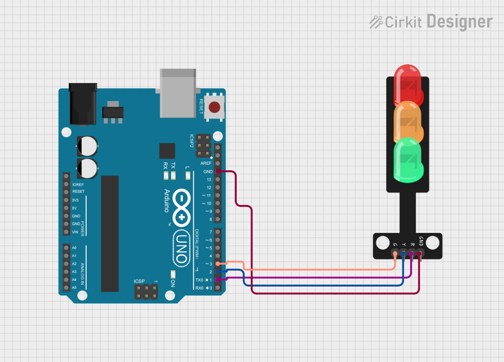
- GND: Connected to the GND pin of the Traffic Light module to establish a common ground.
- D3: Connected to the Green LED of the Traffic Light module.
- D2: Connected to the Yellow LED of the Traffic Light module.
- D1: Connected to the Red LED of the Traffic Light module.
Traffic Light
- Green: Connected to pin D3 on the Arduino UNO.
- Yellow: Connected to pin D2 on the Arduino UNO.
- Red: Connected to pin D1 on the Arduino UNO.
- GND: Connected to the GND pin on the Arduino UNO.
Documented Code
/*
 * This Arduino sketch controls a traffic light system with three LEDs: green,
 * yellow, and red. The green LED is on for 5 seconds, followed by the yellow
 * LED for 2 seconds, and then the red LED for 5 seconds. This cycle repeats
 * indefinitely.
 */

// Pin definitions
const int greenPin = 3;
const int yellowPin = 2;
const int redPin = 1;

void setup() {
  // Initialize the digital pins as outputs
  pinMode(greenPin, OUTPUT);
  pinMode(yellowPin, OUTPUT);
  pinMode(redPin, OUTPUT);
}

void loop() {
  // Green LED on for 5 seconds
  digitalWrite(greenPin, HIGH);
  delay(5000);
  digitalWrite(greenPin, LOW);

  // Yellow LED on for 2 seconds
  digitalWrite(yellowPin, HIGH);
  delay(2000);
  digitalWrite(yellowPin, LOW);

  // Red LED on for 5 seconds
  digitalWrite(redPin, HIGH);
  delay(5000);
  digitalWrite(redPin, LOW);
}
Filename: sketch.ino
Description: The code provided is an Arduino sketch that controls the traffic light system. It defines three pins corresponding to the green, yellow, and red LEDs of the traffic light module. In the setup() function, these pins are configured as outputs. The loop() function then controls the state of each LED, turning them on and off in sequence to simulate a traffic light. The green LED is on for 5 seconds, the yellow LED for 2 seconds, and the red LED for 5 seconds. This cycle repeats indefinitely.