Arduino-Controlled Dual DC Motor Driver for Robotic Wheels
Circuit Documentation
Summary of the Circuit
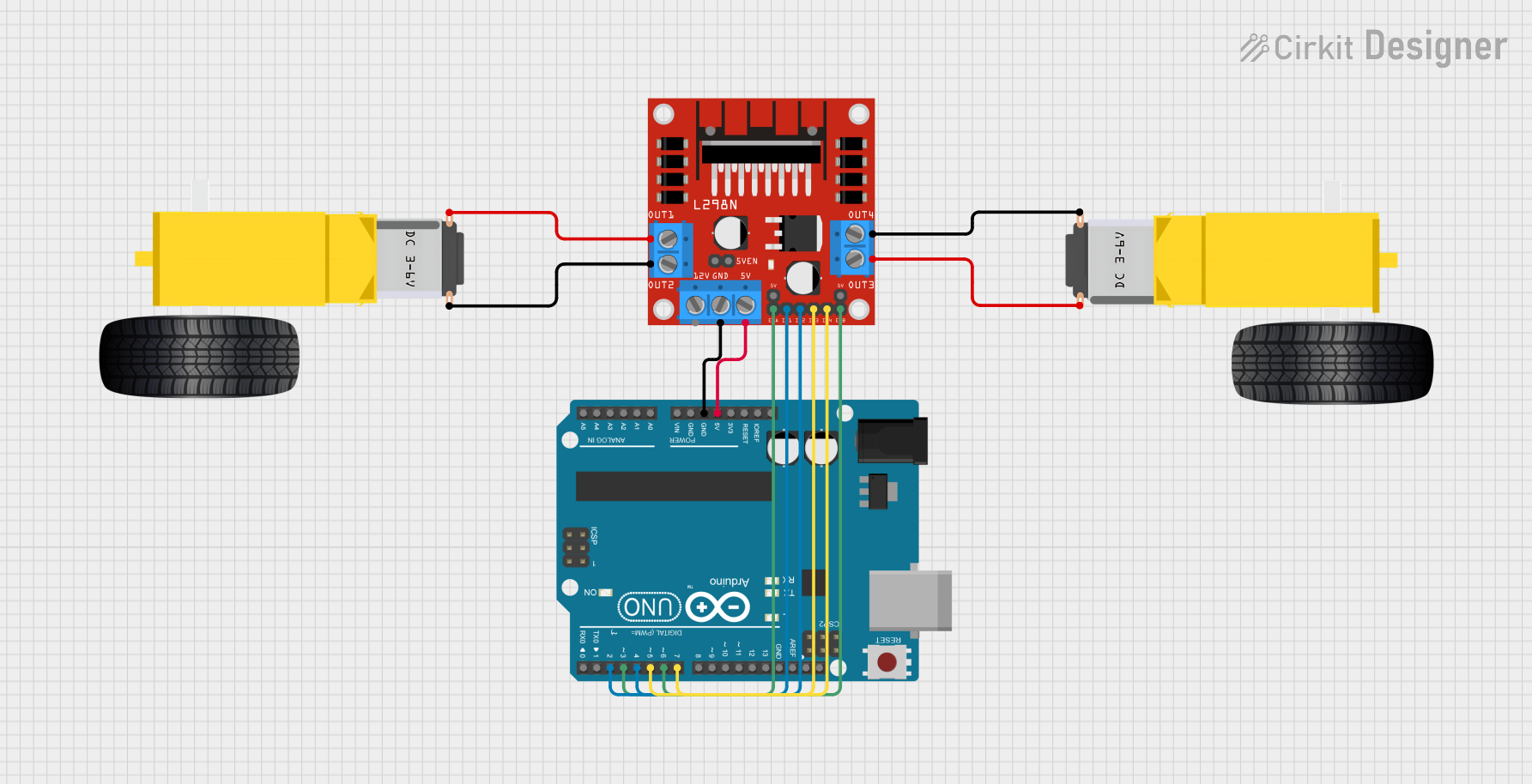
This circuit is designed to control a pair of DC gearmotors using an Arduino UNO microcontroller and an L298N DC motor driver. The Arduino UNO provides the control signals to the L298N driver, which in turn drives the motors. The 5V and GND connections between the Arduino and the L298N ensure that the logic levels are compatible and that there is a common ground reference. The Arduino's digital pins are used to send PWM (Pulse Width Modulation) signals and direction controls to the L298N, which then powers the motors accordingly.
Component List
Arduino UNO
- Description: A microcontroller board based on the ATmega328P.
- Purpose: Acts as the central controller for the circuit, providing logic and control signals to the motor driver.
Gearmotor DC Wheels Right
- Description: A DC gearmotor that is part of the right wheel assembly.
- Purpose: Provides locomotion when powered by the motor driver.
L298N DC motor driver
- Description: A dual H-bridge motor driver capable of driving two DC motors.
- Purpose: Interfaces between the Arduino and the motors, providing the necessary current and direction control.
Gearmotor DC Wheels Left
- Description: A DC gearmotor that is part of the left wheel assembly.
- Purpose: Provides locomotion when powered by the motor driver.
Wiring Details
Arduino UNO
- 5V: Supplies power to the L298N motor driver.
- GND: Common ground with the L298N motor driver.
- D2: Connected to IN1 on the L298N to control the left motor direction.
- D3: Connected to ENA on the L298N to control the speed of the left motor via PWM.
- D4: Connected to IN2 on the L298N to control the left motor direction.
- D5: Connected to IN3 on the L298N to control the right motor direction.
- D6: Connected to ENB on the L298N to control the speed of the right motor via PWM.
- D7: Connected to IN4 on the L298N to control the right motor direction.
Gearmotor DC Wheels Right
- PIN1: Connected to OUT2 on the L298N motor driver.
- PIN2: Connected to OUT1 on the L298N motor driver.
L298N DC motor driver
- 5V: Receives power from the 5V pin of the Arduino UNO.
- GND: Connected to the GND pin of the Arduino UNO.
- IN1, IN2, IN3, IN4: Receive control signals from the Arduino UNO to control the direction of the motors.
- ENA, ENB: Receive PWM signals from the Arduino UNO to control the speed of the motors.
- OUT1, OUT2: Provide power to the Gearmotor DC Wheels Right.
- OUT3, OUT4: Provide power to the Gearmotor DC Wheels Left.
Gearmotor DC Wheels Left
- PIN1: Connected to OUT4 on the L298N motor driver.
- PIN2: Connected to OUT3 on the L298N motor driver.
Documented Code
Arduino UNO Code (sketch.ino)
void setup() {
  // put your setup code here, to run once:

}

void loop() {
  // put your main code here, to run repeatedly:

}
This code template provides the basic structure for the Arduino sketch. The setup() function is intended to contain initialization code that runs once at the start, while the loop() function contains the main logic that will run repeatedly. To control the motors, code will need to be added to set the appropriate pins as outputs and to send PWM signals for speed control and digital signals for direction control.