Arduino LCD Display with Trimmer Potentiometer
Circuit Documentation
Summary
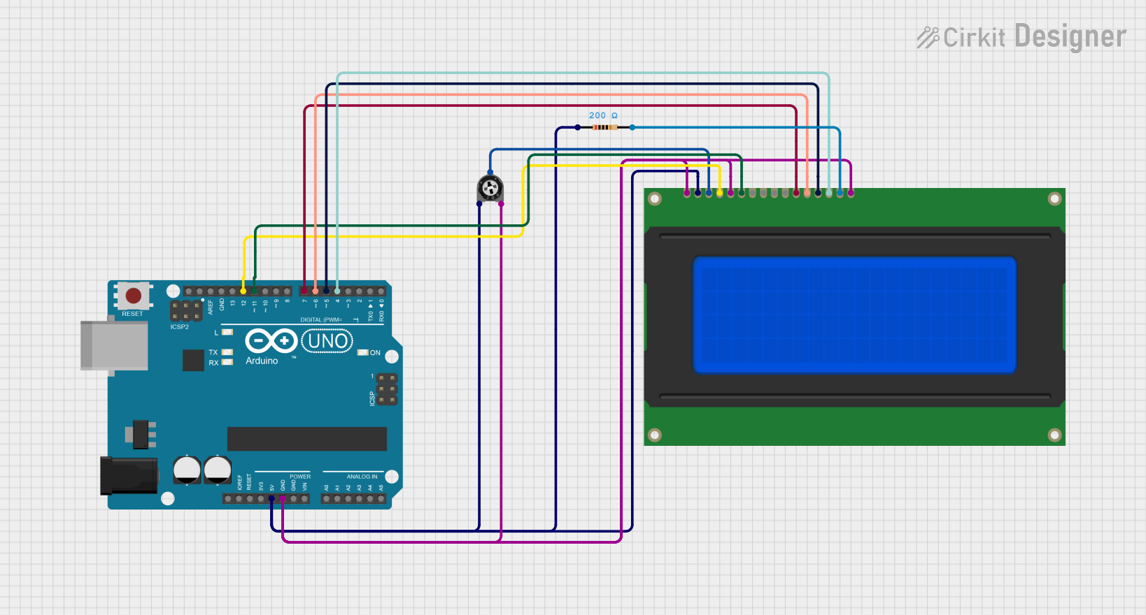
This circuit is designed using an Arduino UNO microcontroller to control a 20x4 LCD display. The circuit includes a trimmer potentiometer for adjusting the display contrast and a resistor for current limiting. The LCD is connected to the Arduino using a 4-bit data interface, allowing for efficient communication and control of the display.
Component List
Arduino UNO
- Description: A microcontroller board based on the ATmega328P. It is used to control the circuit and interface with the LCD.
- Purpose: Acts as the main controller for the circuit, executing the code to manage the LCD display.
Trimmer Potentiometer
- Description: A variable resistor used to adjust the voltage level.
- Purpose: Used to control the contrast of the LCD display.
Resistor
- Description: A passive electrical component that limits the flow of current in a circuit.
- Purpose: Provides a current-limiting function for the LCD display.
LCD 20x4
- Description: A 20x4 character LCD display that can show 20 characters per line and has 4 lines.
- Purpose: Displays information and messages to the user.
Wiring Details
Arduino UNO
5V: Connected to the Trimmer Potentiometer (leg1) and LCD (Vdd).
GND: Connected to the Trimmer Potentiometer (leg2), LCD (Vss, K-), and LCD (R/W).
D12: Connected to the LCD (RS).
D11: Connected to the LCD (E).
D7: Connected to the LCD (DB4).
D6: Connected to the LCD (DB5).
D5: Connected to the LCD (DB6).
D4: Connected to the LCD (DB7).
Trimmer Potentiometer
leg1: Connected to the Arduino UNO (5V).
leg2: Connected to the Arduino UNO (GND).
wiper: Connected to the LCD (Vo).
Resistor
pin1: Connected to the Arduino UNO (5V).
pin2: Connected to the LCD (A+).
LCD 20x4
Vss: Connected to the Arduino UNO (GND).
Vdd: Connected to the Arduino UNO (5V).
Vo: Connected to the Trimmer Potentiometer (wiper).
RS: Connected to the Arduino UNO (D12).
R/W: Connected to the Arduino UNO (GND).
E: Connected to the Arduino UNO (D11).
DB0: Not connected.
DB1: Not connected.
DB2: Not connected.
DB3: Not connected.
DB4: Connected to the Arduino UNO (D7).
DB5: Connected to the Arduino UNO (D6).
DB6: Connected to the Arduino UNO (D5).
DB7: Connected to the Arduino UNO (D4).
A+: Connected to the Resistor (pin2).
K-: Connected to the Arduino UNO (GND).
Documented Code
#include <LiquidCrystal.h>

// Wiring per your circuit:
// RS -> D12, E -> D11, DB4->D7, DB5->D6, DB6->D5, DB7->D4
LiquidCrystal lcd(12, 11, 7, 6, 5, 4);

void setup() {
  lcd.begin(20, 4); // 20 columns, 4 rows
  lcd.clear();

  lcd.setCursor(0, 0);
  lcd.print("Welcome to");
  lcd.setCursor(0, 1);
  lcd.print("Cirkit Designer");

  lcd.setCursor(0, 2);
  lcd.print("LCD built by");
  lcd.setCursor(0, 3);
  lcd.print("Surya Kalyan");
}

void loop() {
  // Nothing else needed
}
This documentation provides a comprehensive overview of the circuit, detailing each component, its purpose, and the wiring connections. The included code initializes the LCD and displays a welcome message.