
Arduino-Controlled Traffic Light System with Ambulance Priority and GSM Notification
View and Edit Project In Cirkit Designer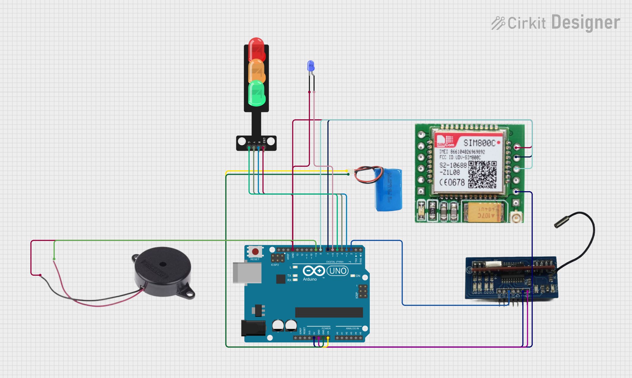
Circuit Documentation
Summary
This circuit is designed to control a traffic light system with an added feature to prioritize the approach of an ambulance. It includes an RF receiver to detect the ambulance signal, a traffic light setup, a blue LED for a special indication, a buzzer for an audible alert, and a GSM module to send notifications to traffic police. The system is powered by a 5V battery and is controlled by an Arduino UNO microcontroller.
Component List
RF Receiver
- Description: A radio frequency receiver module that detects signals from an RF transmitter.
- Pins: D0, D1, D2, D3, GND, VCC
Traffic Light
- Description: A set of LEDs representing a traffic light with green, yellow, and red lights.
- Pins: Green, Yellow, Red, GND
Arduino UNO
- Description: A microcontroller board based on the ATmega328P, used as the main controller for the circuit.
- Pins: UNUSED, IOREF, Reset, 3.3V, 5V, GND, Vin, A0-A5, SCL, SDA, AREF, D0-D13
5V Battery
- Description: A power source for the circuit.
- Pins: Positive, Negative
SIM800c GSM Module
- Description: A GSM/GPRS module used for mobile communication, such as sending SMS messages.
- Pins: SPK-, SPK+, MIC-, MIC+, DTR, RING, GND, TXD, RXD, LINK GND, ANT, VCC(3.7 - 4.2)
LED: Two Pin (blue)
- Description: A blue LED used as a special indicator in the circuit.
- Pins: Cathode, Anode
Buzzer
- Description: An audible alert device.
- Pins: POSITIVE, NEGATIVE
Wiring Details
RF Receiver
- D2 connected to Arduino UNO D2
- VCC connected to 5V net (Arduino UNO 5V)
- GND connected to GND net
Traffic Light
- Green connected to Arduino UNO D5
- Yellow connected to Arduino UNO D4
- Red connected to Arduino UNO D3
- GND connected to GND net
Arduino UNO
- 5V connected to 5V net (RF Receiver VCC, SIM800c GSM Module VCC)
- GND connected to GND net (RF Receiver GND, Traffic Light GND, SIM800c GSM Module GND, LED GND, Buzzer GND)
- Vin connected to 5V Battery Positive
- D2 connected to RF Receiver D2
- D3-D5 connected to Traffic Light Red, Yellow, Green respectively
- D6 connected to LED Anode
- D7 connected to SIM800c GSM Module TXD
- D8 connected to SIM800c GSM Module RXD
- D9 connected to Buzzer POSITIVE
5V Battery
- Positive connected to Arduino UNO Vin
- Negative connected to GND net
SIM800c GSM Module
- VCC(3.7 - 4.2) connected to 5V net
- GND connected to GND net
- TXD connected to Arduino UNO D7
- RXD connected to Arduino UNO D8
LED: Two Pin (blue)
- Anode connected to Arduino UNO D6
- Cathode connected to GND net
Buzzer
- POSITIVE connected to Arduino UNO D9
- NEGATIVE connected to GND net
Documented Code
/*
 * This Arduino sketch controls a traffic light system that prioritizes an
 * ambulance's approach. It uses an RF receiver to detect the ambulance,
 * overrides the standard traffic light cycle, activates a special fourth
 * light, and sends a notification to the traffic police via a GSM module.
 * Additionally, it sounds a buzzer for an audible alert.
 */

#include <SoftwareSerial.h>

// Pin definitions
const int rfReceiverPin = 2;
const int redLightPin = 3;
const int yellowLightPin = 4;
const int greenLightPin = 5;
const int blueLedPin = 6;
const int buzzerPin = 9;
const int gsmTxPin = 7;
const int gsmRxPin = 8;

// GSM module setup
SoftwareSerial gsmSerial(gsmTxPin, gsmRxPin);

void setup() {
  // Initialize serial communication
  Serial.begin(9600);
  gsmSerial.begin(9600);

  // Initialize pins
  pinMode(rfReceiverPin, INPUT);
  pinMode(redLightPin, OUTPUT);
  pinMode(yellowLightPin, OUTPUT);
  pinMode(greenLightPin, OUTPUT);
  pinMode(blueLedPin, OUTPUT);
  pinMode(buzzerPin, OUTPUT);

  // Start with all lights off
  digitalWrite(redLightPin, LOW);
  digitalWrite(yellowLightPin, LOW);
  digitalWrite(greenLightPin, LOW);
  digitalWrite(blueLedPin, LOW);
  digitalWrite(buzzerPin, LOW);
}

void loop() {
  // Check for RF signal
  if (digitalRead(rfReceiverPin) == HIGH) {
    // Ambulance detected
    Serial.println("Ambulance detected!");

    // Turn off standard traffic lights
    digitalWrite(redLightPin, LOW);
    digitalWrite(yellowLightPin, LOW);
    digitalWrite(greenLightPin, LOW);

    // Turn on special fourth light and buzzer
    digitalWrite(blueLedPin, HIGH);
    digitalWrite(buzzerPin, HIGH);

    // Send notification via GSM module
    sendGsmNotification();

    // Keep the fourth light on for a while
    delay(10000); // 10 seconds

    // Turn off special fourth light and buzzer
    digitalWrite(blueLedPin, LOW);
    digitalWrite(buzzerPin, LOW);
  } else {
    // Standard traffic light cycle
    digitalWrite(redLightPin, HIGH);
    delay(5000); // Red for 5 seconds
    digitalWrite(redLightPin, LOW);

    digitalWrite(yellowLightPin, HIGH);
    delay(2000); // Yellow for 2 seconds
    digitalWrite(yellowLightPin, LOW);

    digitalWrite(greenLightPin, HIGH);
    delay(5000); // Green for 5 seconds
    digitalWrite(greenLightPin, LOW);
  }
}

void sendGsmNotification() {
  gsmSerial.println("AT+CMGF=1"); // Set SMS mode to text
  delay(100);
  gsmSerial.println("AT+CMGS=\"+1234567890\""); // Replace with actual number
  delay(100);
  gsmSerial.print("Ambulance approaching. Clear the lane.");
  delay(100);
  gsmSerial.write(26); // ASCII code for Ctrl+Z to send the message
  delay(100);
}
Note: The code provided is for the Arduino UNO microcontroller. The GSM module phone number in the sendGsmNotification function should be replaced with the actual number where notifications are to be sent.