
Arduino UNO Controlled Touch-Activated Relay with LED Indicator
View and Edit Project In Cirkit Designer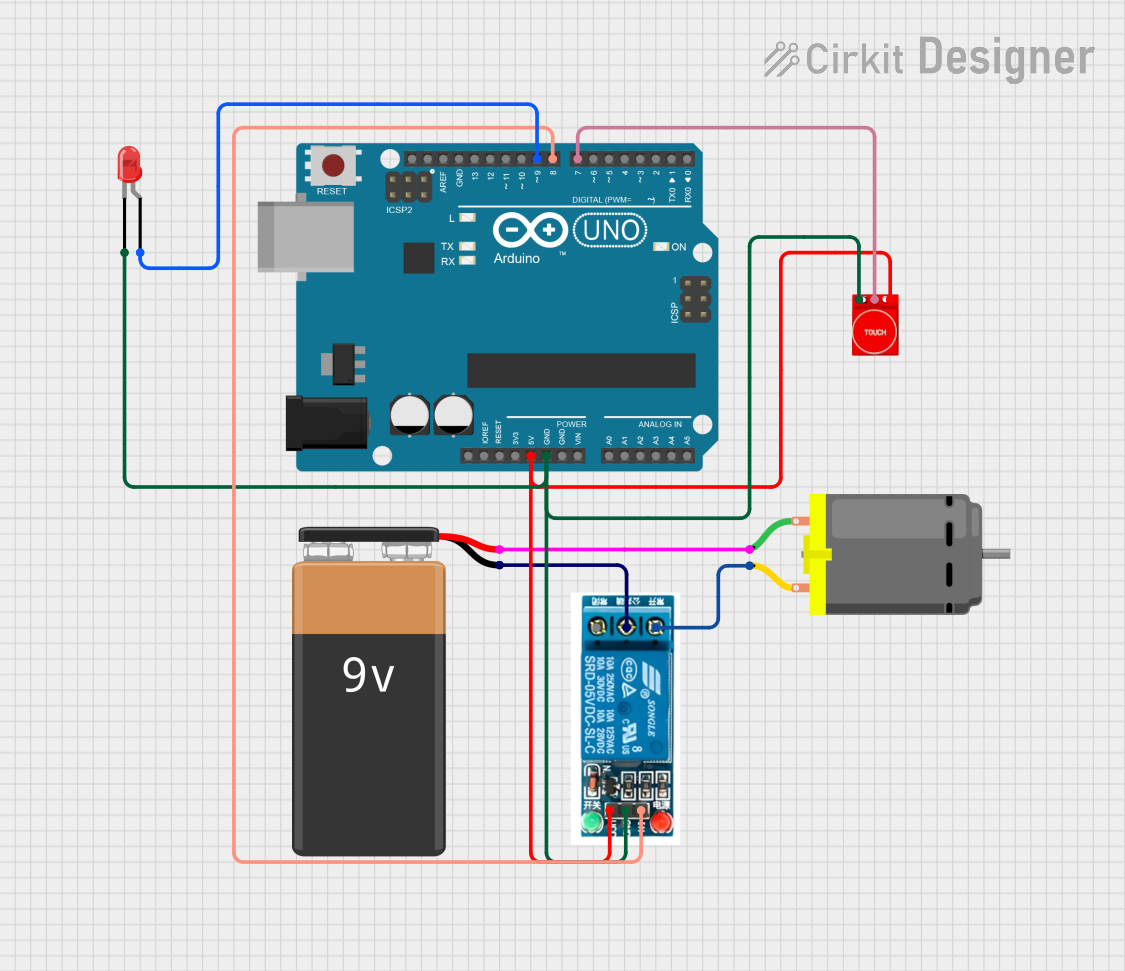
Circuit Documentation
Summary of the Circuit
This circuit is designed to control a DC motor and an LED using an Arduino UNO microcontroller in response to input from a touch sensor. The motor is powered by a 9V battery and switched on and off by a 5V relay. The relay is controlled by the Arduino, which also directly controls the LED. The touch sensor provides a user interface to toggle the state of the motor and the LED.
Component List
Arduino UNO
- Microcontroller board based on the ATmega328P
- It has 14 digital input/output pins, 6 analog inputs, a 16 MHz quartz crystal, a USB connection, a power jack, an ICSP header, and a reset button.
9V Battery
- Standard 9V battery used to provide power to the DC motor through the relay.
5V Relay
- An electromechanical switch used to control high power devices; it has a coil rated at 5V.
- Pins: Normally Open, Common terminal, Normally Closed, Input, Ground, VCC
DC Motor
- A simple electric motor that runs on direct current (DC) power.
- Pins: pin 1, pin 2
Touch Sensor TTP233
- A capacitive touch sensor module based on the TTP233 touch detector IC.
- Pins: Ground, I/O, VCC
LED: Two Pin (red)
- A basic red LED for indication purposes.
- Pins: cathode, anode
Wiring Details
Arduino UNO
- 5V: Connected to VCC of the Touch Sensor TTP233 and 5V relay.
- GND: Connected to GND of the Touch Sensor TTP233, 5V relay, and cathode of the LED.
- D9: Connected to the anode of the LED.
- D8: Connected to the Input of the 5V relay.
- D7: Connected to the I/O of the Touch Sensor TTP233.
9V Battery
- "+": Connected to pin 1 of the DC Motor.
- "-": Connected to the Common terminal of the 5V relay.
5V Relay
- VCC: Connected to 5V of the Arduino UNO.
- GND: Connected to GND of the Arduino UNO.
- In: Connected to D8 of the Arduino UNO.
- Common terminal: Connected to "-" of the 9V Battery.
- Normally Open: Connected to pin 2 of the DC Motor.
DC Motor
- pin 1: Connected to "+" of the 9V Battery.
- pin 2: Connected to Normally Open of the 5V relay.
Touch Sensor TTP233
- VCC: Connected to 5V of the Arduino UNO.
- GND: Connected to GND of the Arduino UNO.
- I/O: Connected to D7 of the Arduino UNO.
LED: Two Pin (red)
- cathode: Connected to GND of the Arduino UNO.
- anode: Connected to D9 of the Arduino UNO.
Documented Code
// Code for controlling a DC motor and LED using a touch sensor
const int relay1 = 8; // Relay control pin
const int led = 9;    // LED control pin
const int touchSensor = 7; // Touch sensor input pin

void setup() {
  pinMode(relay1, OUTPUT); // Set relay pin as output
  pinMode(led, OUTPUT);    // Set LED pin as output
  pinMode(touchSensor, INPUT); // Set touch sensor pin as input
  digitalWrite(relay1, HIGH); // Initialize relay as off
  digitalWrite(led, LOW);     // Initialize LED as off
}

void loop() {
  int sensorValue = digitalRead(touchSensor); // Read the touch sensor value

  if (sensorValue == HIGH) {
    // If the touch sensor is touched
    digitalWrite(relay1, LOW); // Turn on the relay (motor on)
    digitalWrite(led, HIGH);   // Turn on the LED
  } else {
    // If the touch sensor is not touched
    digitalWrite(relay1, HIGH); // Turn off the relay (motor off)
    digitalWrite(led, LOW);     // Turn off the LED
  }

  delay(100); // Small delay to debounce the touch sensor
}
This code is designed to run on the Arduino UNO microcontroller. It initializes the relay, LED, and touch sensor pins. In the main loop, it reads the state of the touch sensor. If the sensor is touched, it activates the relay (which turns on the motor) and the LED. If the sensor is not touched, it deactivates the relay and the LED. The delay at the end of the loop helps to debounce the touch sensor input.