
Circuit Documentation
Summary
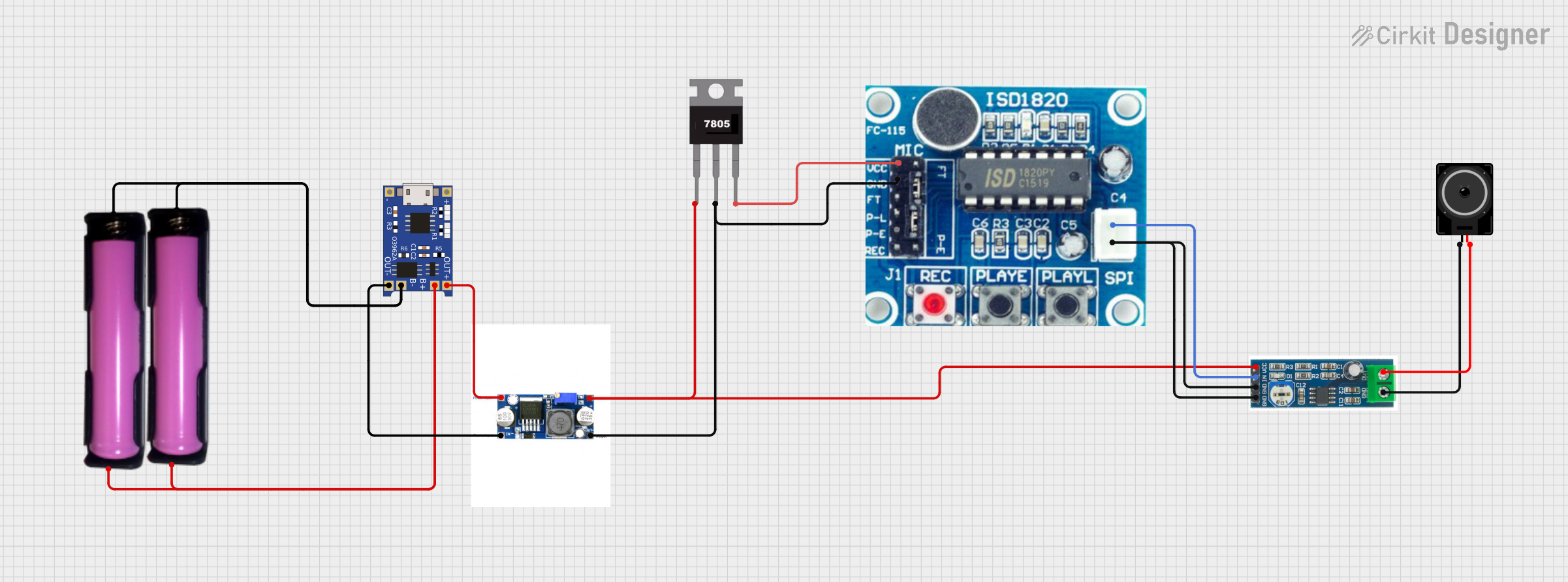
This circuit is designed to charge and boost the voltage of a battery to power an audio playback and amplification system. It consists of two 18650 lithium-ion batteries in holders, a TP4056 lithium battery charger module, an XL 6009 DC-DC boost converter module, a 7805 voltage regulator, an ISD1820 voice recording and playback module, an LM386 audio amplifier module, and a loudspeaker. The circuit is intended to record audio via the ISD1820 module and play it back through the loudspeaker, with the LM386 module amplifying the audio signal.
Component List
18650 in holder
- Description: A battery holder for a single 18650 lithium-ion cell.
- Pins: GND, VCC
TP4056
- Description: A lithium battery charger module for charging a single cell 18650 lithium-ion battery.
- Pins: OUT-, B-, B+, OUT+, IN-, IN+
XL 6009 Boost Module
- Description: A DC-DC boost converter module capable of stepping up a lower voltage to a higher voltage.
- Pins: input +, Input -, Out +, Out -
7805
- Description: A voltage regulator that outputs a steady 5V from a higher input voltage.
- Pins: Vin, Gnd, Vout
ISD1820
- Description: A voice recording and playback module.
- Pins: VCC, GND, P-E, Sp1, SP2
LM386 audio amplifier module
- Description: An audio amplifier module based on the LM386 amplifier IC.
- Pins: VCC, IN, GND, OUT
Loudspeaker
- Description: An electroacoustic transducer that converts an electrical audio signal into a corresponding sound.
- Pins: pin1, pin2
Wiring Details
18650 in holder
- GND: Connected to the GND pin of the TP4056 and the other 18650 battery holder.
- VCC: Connected to the B+ pin of the TP4056 and the other 18650 battery holder.
TP4056
- OUT-: Connected to the Input - pin of the XL 6009 Boost Module.
- B-: Connected to the GND pin of both 18650 battery holders.
- B+: Connected to the VCC pin of both 18650 battery holders.
- OUT+: Connected to the input + pin of the XL 6009 Boost Module.
XL 6009 Boost Module
- input +: Connected to the OUT+ pin of the TP4056.
- Input -: Connected to the OUT- pin of the TP4056.
- Out +: Connected to the VCC pin of the LM386 audio amplifier module and the Vin pin of the 7805 voltage regulator.
- Out -: Connected to the GND pin of the ISD1820, the Gnd pin of the 7805 voltage regulator, and the GND pin of the LM386 audio amplifier module.
7805
- Vin: Connected to the Out + pin of the XL 6009 Boost Module.
- Gnd: Connected to the Out - pin of the XL 6009 Boost Module.
- Vout: Connected to the VCC pin of the ISD1820.
ISD1820
- GND: Connected to the Out - pin of the XL 6009 Boost Module.
- VCC: Connected to the Vout pin of the 7805 voltage regulator.
- P-E: Not connected in the provided net list.
- Sp1: Connected to the IN pin of the LM386 audio amplifier module.
- SP2: Connected to the GND pin of the LM386 audio amplifier module.
LM386 audio amplifier module
- VCC: Connected to the Out + pin of the XL 6009 Boost Module.
- IN: Connected to the Sp1 pin of the ISD1820.
- GND: Connected to the Out - pin of the XL 6009 Boost Module and the SP2 pin of the ISD1820.
- OUT: Connected to the pin2 of the Loudspeaker.
Loudspeaker
- pin1: Connected to the GND pin of the LM386 audio amplifier module.
- pin2: Connected to the OUT pin of the LM386 audio amplifier module.
Documented Code
There is no microcontroller code provided for this circuit. If a microcontroller is added to the circuit in the future, the code will be documented in this section.