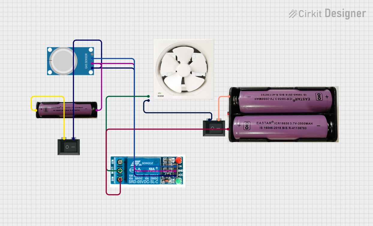
MQ-4 Gas Sensor Controlled Exhaust Fan System

Circuit Documentation
Summary of the Circuit
This circuit appears to be designed to detect a certain condition using an MQ-4 sensor, which is typically used for detecting methane and natural gas concentrations in the air. Upon detection, the circuit can activate a 5V relay, which in turn can control an external device such as an exhaust fan. The circuit includes two power sources, one at 3.7V and another at 7.4V, and two rocker switches to control the power flow. The relay can switch between the normally closed state, connected to the 7.4V power source, and the common terminal, which is connected to the exhaust fan. The exhaust fan is also connected to a neutral line through another rocker switch. The circuit does not include any microcontroller code, suggesting that the MQ-4 sensor's digital output is used directly to control the relay.
Component List
MQ-4 Gas Sensor
- Pins: A0, D0, GND, VCC
- Description: A gas sensor used for detecting methane and natural gas concentrations in the air.
5V Relay
- Pins: Normally Open, Common terminal, Normally Closed, In, GND, VCC
- Description: An electromechanical switch used for turning on/off an external circuit or device.
3.7V Power Source
- Pins: +, -
- Description: Provides a 3.7V power supply to the circuit.
Rocker Switch (SPST)
- Pins: 1, 2
- Description: A single-pole single-throw switch used to control the connection of a circuit.
7.4V Power Source
- Pins: +, -
- Description: Provides a 7.4V power supply to the circuit.
Exhaust Fan 12"
- Pins: Live, Neutral
- Description: An external device that can be controlled by the circuit to ventilate an area.
Wiring Details
MQ-4 Gas Sensor
- D0: Connected to the "In" pin of the 5V relay.
- GND: Shared ground with the 5V relay and the 3.7V power source.
- VCC: Connected to the "2" pin of one of the Rocker Switches (SPST).
5V Relay
- In: Connected to the "D0" pin of the MQ-4 gas sensor.
- GND: Shared ground with the MQ-4 sensor and the 3.7V power source.
- VCC: Connected to the "2" pin of one of the Rocker Switches (SPST).
- Common terminal: Connected to the "Live" pin of the Exhaust Fan 12".
- Normally Closed: Connected to the "+" pin of the 7.4V power source.
3.7V Power Source
- - (Negative): Shared ground with the MQ-4 sensor and the 5V relay.
- + (Positive): Connected to the "1" pin of one of the Rocker Switches (SPST).
Rocker Switch (SPST)
- 1: One switch is connected to the "+" pin of the 3.7V power source, and the other is connected to the "Neutral" pin of the Exhaust Fan 12".
- 2: One switch is connected to the "VCC" pins of both the MQ-4 sensor and the 5V relay, and the other is connected to the "-" pin of the 7.4V power source.
7.4V Power Source
- - (Negative): Connected to the "2" pin of one of the Rocker Switches (SPST).
- + (Positive): Connected to the "Normally Closed" pin of the 5V relay.
Exhaust Fan 12"
- Live: Connected to the "Common terminal" pin of the 5V relay.
- Neutral: Connected to the "1" pin of one of the Rocker Switches (SPST).
Documented Code
There is no embedded code provided for any microcontrollers in this circuit. The operation of the circuit is based on the direct interaction between the MQ-4 sensor and the 5V relay, which does not require any programming.