Arduino UNO Bluetooth-Controlled Dual Stepper Motor System
Circuit Documentation
Summary
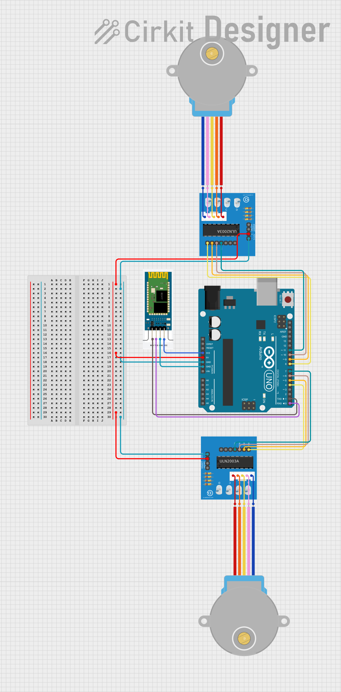
This circuit involves an Arduino UNO microcontroller, two 28BYJ-48 stepper motors, two ULN2003A breakout boards, and an HC-06 Bluetooth module. The Arduino UNO controls the stepper motors via the ULN2003A breakout boards and communicates with a Bluetooth device using the HC-06 module. The stepper motors are used for precise rotational control, and the Bluetooth module allows for wireless control of the motors.
Component List
Arduino UNO
- Description: A microcontroller board based on the ATmega328P.
- Pins: UNUSED, IOREF, Reset, 3.3V, 5V, GND, Vin, A0, A1, A2, A3, A4, A5, SCL, SDA, AREF, D13, D12, D11, D10, D9, D8, D7, D6, D5, D4, D3, D2, D1, D0
28BYJ-48 Stepper Motor
- Description: A small, inexpensive stepper motor commonly used in various applications.
- Pins: BLUE, PINK, YELLOW, ORANGE, RED
HC-06 Bluetooth Module
- Description: A Bluetooth module used for wireless communication.
- Pins: RXD, TXD, GND, VCC
ULN2003A Breakout Board
- Description: A driver board for controlling stepper motors.
- Pins: In 1, In 2, In 3, In 4, In 5, In 6, In 7, 0V, +5V, ON/OFF jumper switch, BLUE wire, PINK wire, YELLOW wire, ORANGE wire, RED wire
Wiring Details
Arduino UNO
- 5V: Connected to +5V on both ULN2003A breakout boards.
- GND: Connected to 0V on both ULN2003A breakout boards and GND on the HC-06 Bluetooth module.
- 3.3V: Connected to VCC on the HC-06 Bluetooth module.
- D11: Connected to In 4 on the first ULN2003A breakout board.
- D10: Connected to In 3 on the first ULN2003A breakout board.
- D9: Connected to In 2 on the first ULN2003A breakout board.
- D8: Connected to In 1 on the first ULN2003A breakout board.
- D7: Connected to In 4 on the second ULN2003A breakout board.
- D6: Connected to In 3 on the second ULN2003A breakout board.
- D5: Connected to In 2 on the second ULN2003A breakout board.
- D4: Connected to In 1 on the second ULN2003A breakout board.
- D1: Connected to RXD on the HC-06 Bluetooth module.
- D0: Connected to TXD on the HC-06 Bluetooth module.
28BYJ-48 Stepper Motor (First Motor)
- BLUE: Connected to BLUE wire on the first ULN2003A breakout board.
- PINK: Connected to PINK wire on the first ULN2003A breakout board.
- YELLOW: Connected to YELLOW wire on the first ULN2003A breakout board.
- ORANGE: Connected to ORANGE wire on the first ULN2003A breakout board.
- RED: Connected to RED wire on the first ULN2003A breakout board.
28BYJ-48 Stepper Motor (Second Motor)
- BLUE: Connected to BLUE wire on the second ULN2003A breakout board.
- PINK: Connected to PINK wire on the second ULN2003A breakout board.
- YELLOW: Connected to YELLOW wire on the second ULN2003A breakout board.
- ORANGE: Connected to ORANGE wire on the second ULN2003A breakout board.
- RED: Connected to RED wire on the second ULN2003A breakout board.
HC-06 Bluetooth Module
- VCC: Connected to 3.3V on the Arduino UNO.
- GND: Connected to GND on the Arduino UNO.
- RXD: Connected to D1 on the Arduino UNO.
- TXD: Connected to D0 on the Arduino UNO.
ULN2003A Breakout Board (First Board)
- +5V: Connected to 5V on the Arduino UNO.
- 0V: Connected to GND on the Arduino UNO.
- In 1: Connected to D8 on the Arduino UNO.
- In 2: Connected to D9 on the Arduino UNO.
- In 3: Connected to D10 on the Arduino UNO.
- In 4: Connected to D11 on the Arduino UNO.
- BLUE wire: Connected to BLUE on the first 28BYJ-48 stepper motor.
- PINK wire: Connected to PINK on the first 28BYJ-48 stepper motor.
- YELLOW wire: Connected to YELLOW on the first 28BYJ-48 stepper motor.
- ORANGE wire: Connected to ORANGE on the first 28BYJ-48 stepper motor.
- RED wire: Connected to RED on the first 28BYJ-48 stepper motor.
ULN2003A Breakout Board (Second Board)
- +5V: Connected to 5V on the Arduino UNO.
- 0V: Connected to GND on the Arduino UNO.
- In 1: Connected to D4 on the Arduino UNO.
- In 2: Connected to D5 on the Arduino UNO.
- In 3: Connected to D6 on the Arduino UNO.
- In 4: Connected to D7 on the Arduino UNO.
- BLUE wire: Connected to BLUE on the second 28BYJ-48 stepper motor.
- PINK wire: Connected to PINK on the second 28BYJ-48 stepper motor.
- YELLOW wire: Connected to YELLOW on the second 28BYJ-48 stepper motor.
- ORANGE wire: Connected to ORANGE on the second 28BYJ-48 stepper motor.
- RED wire: Connected to RED on the second 28BYJ-48 stepper motor.
Code Documentation
#include <AccelStepper.h>

// Define the pins for motor 1
AccelStepper motor1(AccelStepper::HALF4WIRE, 8, 10, 9, 11);

// Define the pins for motor 2
AccelStepper motor2(AccelStepper::HALF4WIRE, 4, 6, 5, 7);

// Set initial rotation speed
const int rotationSpeed = 500;

void setup() {
  // Set up the serial communication for Bluetooth
  Serial.begin(9600);

  motor1.setMaxSpeed(rotationSpeed);
  motor1.setAcceleration(500);
  motor1.setCurrentPosition(0);

  motor2.setMaxSpeed(rotationSpeed);
  motor2.setAcceleration(500);
  motor2.setCurrentPosition(0);
}

void loop() {
  // Check if data is available from the Bluetooth app
  if (Serial.available() > 0) {
    char command = Serial.read();

    // Write commands for the app
    switch (command) {
      case 'F':  // Start both motors rotating forward
        motor1.setSpeed(rotationSpeed);
        motor2.setSpeed(rotationSpeed);
        motor1.enableOutputs();
        motor2.enableOutputs();
        break;
      case 'B':  // Start both motors rotating backward
        motor1.setSpeed(-rotationSpeed);
        motor2.setSpeed(-rotationSpeed);
        motor1.enableOutputs();
        motor2.enableOutputs();
        break;
      case 'S':  // Stop and disconnect both motors
        motor1.setSpeed(0);       // Set speed to 0 to stop immediately
        motor2.setSpeed(0);       // Set speed to 0 to stop immediately
        motor1.disableOutputs();  // Disable outputs to disconnect motors
        motor2.disableOutputs();  // Disable outputs to disconnect motors
        break;
      default:
        // Ignore any other commands
        break;
    }
  }

  // Run motors
  motor1.runSpeed();
  motor2.runSpeed();
}
This code uses the AccelStepper library to control two stepper motors. The motors are controlled based on commands received via Bluetooth. The commands 'F', 'B', and 'S' are used to move the motors forward, backward, and stop them, respectively. The motors' speed and acceleration are set during the setup phase, and the loop continuously checks for incoming Bluetooth commands to control the motors accordingly.