
ESP32 and Arduino UNO Based Smart Temperature Monitoring System with LoRa Communication
View and Edit Project In Cirkit Designer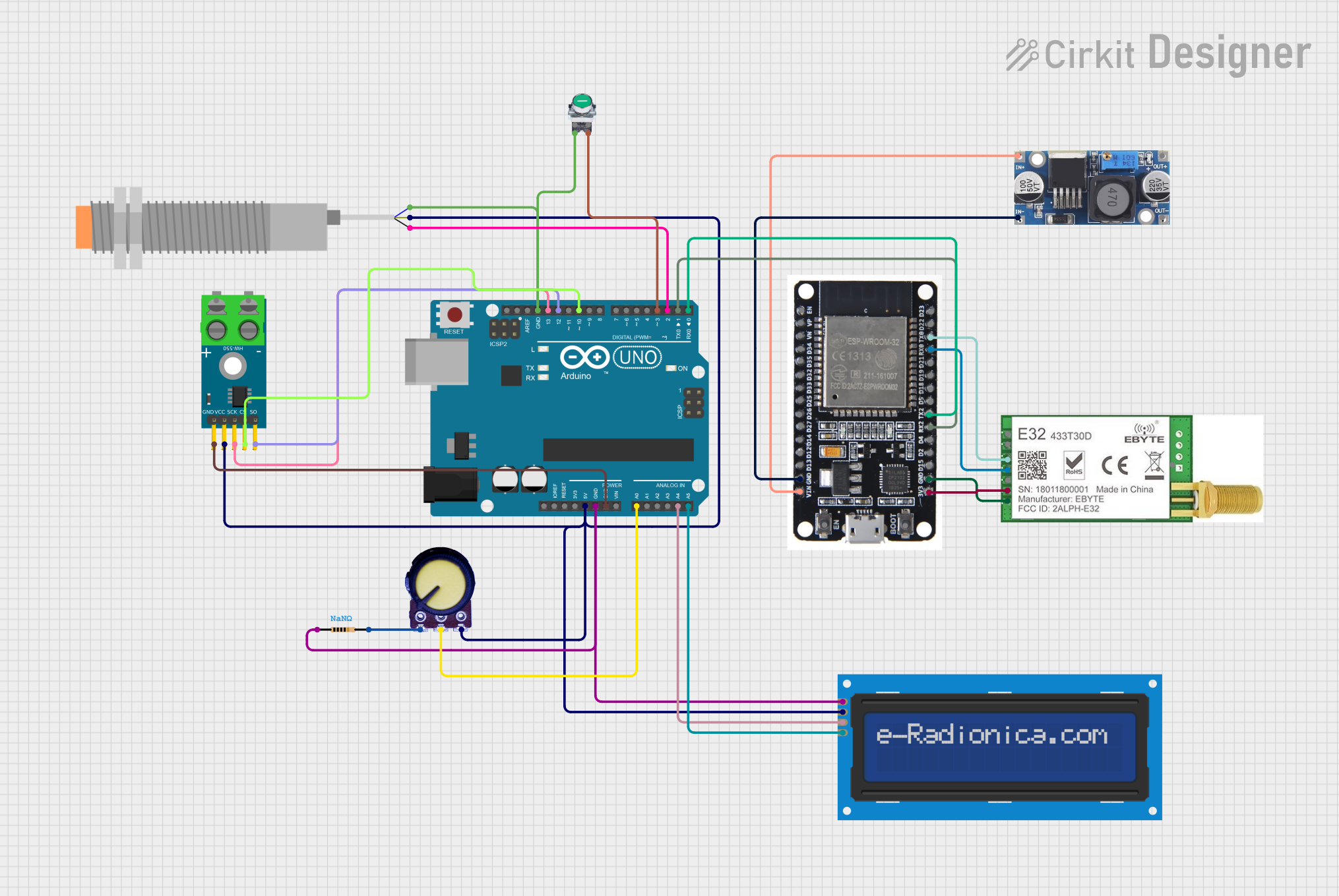
Circuit Documentation
Summary
This circuit involves multiple components including an ESP32, Arduino UNO, MAX6675 Module, LCD screen, LoRa module, pushbutton, potentiometer, resistor, and an inductive proximity sensor. The circuit is designed to interface these components for various functionalities such as temperature sensing, display, wireless communication, and user input.
Component List
MAX6675 Module
- Description: Thermocouple-to-Digital Converter
- Pins: GND, VCC, SCK, CS, SO, -, +
Pushbutton START
- Description: Momentary Pushbutton
- Pins: NC, NO
LCD screen 16x2 I2C
- Description: 16x2 Character LCD with I2C Interface
- Pins: SCL, SDA, VCC, GND
ESP32
- Description: Wi-Fi and Bluetooth Microcontroller
- Pins: EN, VP, VN, D34, D35, D32, D33, D25, D26, D27, D14, D12, D13, GND, VIN, 3V3, D15, D2, D4, RX2, TX2, D5, D18, D19, D21, RX0, TX0, D22, D23, BOOT
LoRa Module
- Description: Long Range Wireless Communication Module
- Pins: M0, M1, RXD, TXD, AUX, VCC, GND
48V to 12V Converter
- Description: Voltage Converter
- Pins: out+, out--, in+, in--
Resistor
- Description: Passive Electrical Component
- Pins: pin1, pin2
- Properties: Resistance: NaN Ohms
Potentiometer
- Description: Variable Resistor
- Pins: GND, Output, VCC
Arduino UNO
- Description: Microcontroller Board
- Pins: UNUSED, IOREF, Reset, 3.3V, 5V, GND, Vin, A0, A1, A2, A3, A4, A5, SCL, SDA, AREF, D13, D12, D11, D10, D9, D8, D7, D6, D5, D4, D3, D2, D1, D0
LJ18A3-H-ZBX Inductive Proximity Sensor
- Description: Inductive Proximity Sensor
- Pins: VO (BLU), VI (BRN), SIG (BLK)
Wiring Details
MAX6675 Module
- GND connected to Arduino UNO GND
- VCC connected to Arduino UNO 5V
- SCK connected to Arduino UNO D13
- CS connected to Arduino UNO D10
- SO connected to Arduino UNO D12
Pushbutton START
- NO connected to Arduino UNO GND
- NO connected to Arduino UNO D3
LCD screen 16x2 I2C
- SCL connected to Arduino UNO A5
- SDA connected to Arduino UNO A4
- VCC connected to Arduino UNO 5V
- GND connected to Resistor pin1 and Arduino UNO GND
ESP32
- TX0 connected to LoRa RXD
- RX0 connected to LoRa TXD
- 3V3 connected to LoRa VCC
- GND connected to LoRa GND
- VIN connected to 48V to 12V Converter in+
- GND connected to 48V to 12V Converter in--
- RX2 connected to Arduino UNO D1
- TX2 connected to Arduino UNO D0
LoRa Module
- RXD connected to ESP32 TX0
- TXD connected to ESP32 RX0
- VCC connected to ESP32 3V3
- GND connected to ESP32 GND
48V to 12V Converter
- in+ connected to ESP32 VIN
- in-- connected to ESP32 GND
Resistor
- pin1 connected to LCD screen GND
- pin2 connected to Potentiometer GND
Potentiometer
- VCC connected to Arduino UNO 5V
- Output connected to Arduino UNO A0
- GND connected to Resistor pin2
Arduino UNO
- GND connected to MAX6675 Module GND, Pushbutton NO, LCD screen GND, Resistor pin1, Inductive Proximity Sensor VO (BLU)
- 5V connected to MAX6675 Module VCC, LCD screen VCC, Potentiometer VCC
- D13 connected to MAX6675 Module SCK
- D12 connected to MAX6675 Module SO
- D10 connected to MAX6675 Module CS
- D3 connected to Pushbutton NO
- A5 connected to LCD screen SCL
- A4 connected to LCD screen SDA
- A0 connected to Potentiometer Output
- D1 connected to ESP32 RX2
- D0 connected to ESP32 TX2
- D2 connected to Inductive Proximity Sensor SIG (BLK)
LJ18A3-H-ZBX Inductive Proximity Sensor
- VI (BRN) connected to Arduino UNO 5V
- VO (BLU) connected to Pushbutton NO and Arduino UNO GND
- SIG (BLK) connected to Arduino UNO D2
Documented Code
Arduino UNO Code (sketch.ino)
void setup() {
  // put your setup code here, to run once:

}

void loop() {
  // put your main code here, to run repeatedly:

}
Additional Documentation (documentation.txt)
This documentation provides a comprehensive overview of the circuit, including a detailed list of components, their wiring connections, and the code used in the microcontroller.