Cirkit Designer
Your all-in-one circuit design IDE
Home /
Project Documentation
Arduino-Controlled IR Receiver with Multiple LED Indicators
Circuit Documentation
Summary of the Circuit
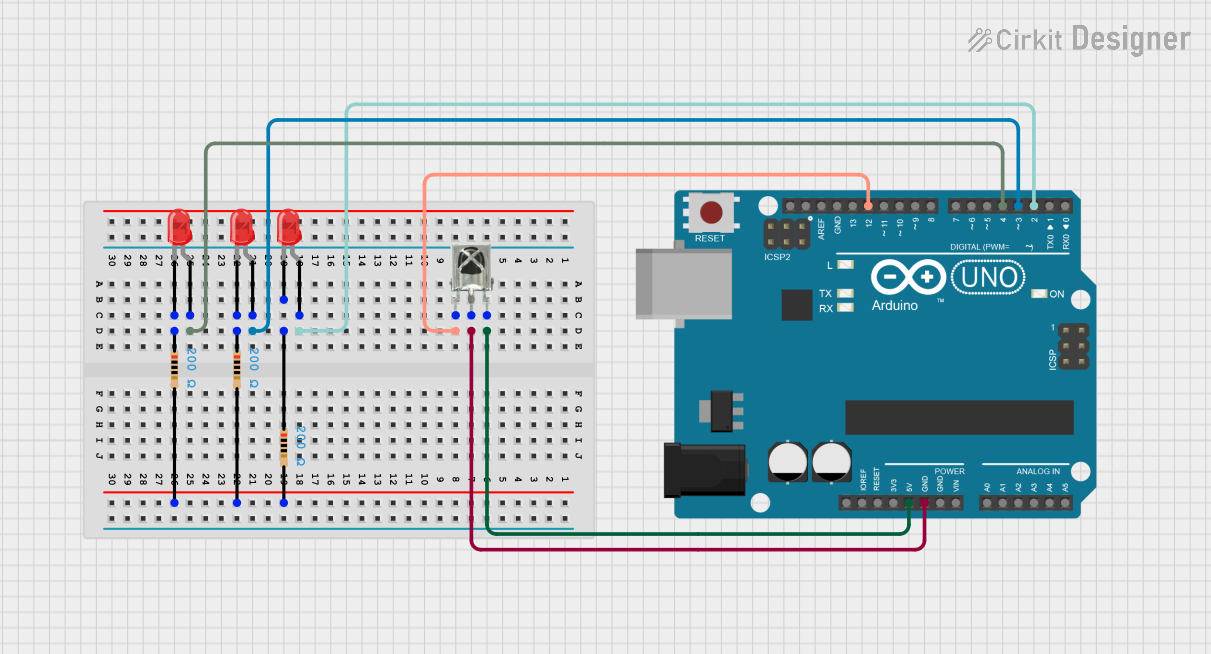
This circuit is designed to interface an Arduino UNO with a VS1838B IR Receiver and three red LEDs, each with its own current-limiting resistor. The Arduino UNO is used as the central processing unit, capable of receiving signals from the IR receiver and controlling the state of the LEDs. The IR receiver is powered by the Arduino and sends its output signal to one of the Arduino's digital pins. Each LED is connected to a different digital pin on the Arduino and is protected by a resistor to limit the current through the LED.
Component List
Arduino UNO
- Description: A microcontroller board based on the ATmega328P.
- Pins: UNUSED, IOREF, Reset, 3.3V, 5V, GND, Vin, A0-A5, SCL, SDA, AREF, D0-D13.
VS1838B IR Receiver
- Description: An infrared receiver tuned to receive IR signals at 38kHz.
- Pins: OUT, GND, VCC.
LEDs: Two Pin (red)
- Description: Standard red LEDs with two pins: anode and cathode.
- Pins: cathode, anode.
Resistors
- Description: Resistors with a resistance value of 200 Ohms.
- Pins: pin1, pin2.
Wiring Details
Arduino UNO
- 5V connected to the VCC of the VS1838B IR Receiver.
- GND connected to the GND of the VS1838B IR Receiver.
- D12 connected to the OUT pin of the VS1838B IR Receiver.
- D2 connected to the anode of the first red LED.
- D3 connected to the anode of the second red LED.
- D4 connected to the anode of the third red LED.
VS1838B IR Receiver
- VCC connected to the 5V of the Arduino UNO.
- GND connected to the GND of the Arduino UNO.
- OUT connected to the D12 of the Arduino UNO.
LEDs: Two Pin (red)
- Anode of the first LED connected to D2 of the Arduino UNO.
- Cathode of the first LED connected to pin1 of the first resistor.
- Anode of the second LED connected to D3 of the Arduino UNO.
- Cathode of the second LED connected to pin1 of the second resistor.
- Anode of the third LED connected to D4 of the Arduino UNO.
- Cathode of the third LED connected to pin1 of the third resistor.
Resistors
- Pin1 of the first resistor connected to the cathode of the first LED.
- Pin2 of the first resistor connected to the common ground net with the other two resistors.
- Pin1 of the second resistor connected to the cathode of the second LED.
- Pin2 of the second resistor connected to the common ground net with the other two resistors.
- Pin1 of the third resistor connected to the cathode of the third LED.
- Pin2 of the third resistor connected to the common ground net with the other two resistors.
Documented Code
Arduino UNO Code (sketch.ino)
void setup() {
  // put your setup code here, to run once:

}

void loop() {
  // put your main code here, to run repeatedly:

}
Additional Notes (documentation.txt)
No additional code documentation was provided.