Cirkit Designer
Your all-in-one circuit design IDE
Home /
Project Documentation
Wi-Fi Controlled Temperature and Humidity Monitor with LED Indicators and Buzzer
Circuit Documentation
Summary
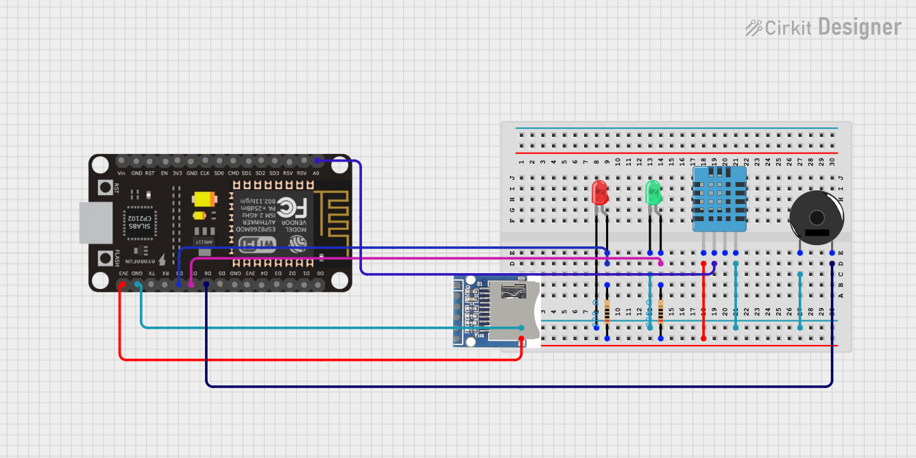
This circuit involves an ESP8266 NodeMCU microcontroller interfacing with various components including LEDs, resistors, a DHT11 humidity and temperature sensor, an SD card module, and a piezo buzzer. The circuit is designed to demonstrate basic input/output operations, sensor data acquisition, and storage capabilities.
Component List
LED: Two Pin (red)
- Description: A red LED with two pins: cathode and anode.
- Purpose: Visual indicator.
LED: Two Pin (green)
- Description: A green LED with two pins: cathode and anode.
- Purpose: Visual indicator.
Resistor (200 Ohms)
- Description: A resistor with a resistance of 200 Ohms.
- Purpose: Current limiting for LEDs.
DHT11 Humidity and Temperature Sensor
- Description: A sensor for measuring humidity and temperature.
- Purpose: Environmental data acquisition.
SD SDHC
- Description: An SD card module for data storage.
- Purpose: Data storage.
ESP8266 NodeMCU
- Description: A microcontroller with Wi-Fi capabilities.
- Purpose: Central control unit.
Piezo Buzzer
- Description: A piezoelectric buzzer with two pins.
- Purpose: Audio indicator.
Wiring Details
LED: Two Pin (red)
- Anode: Connected to pin2 of a 200 Ohm resistor and to D8 of the ESP8266 NodeMCU.
- Cathode: Connected to the cathode of the green LED, GND of the DHT11 sensor, pin 1 of the piezo buzzer, and GND of the ESP8266 NodeMCU.
LED: Two Pin (green)
- Anode: Connected to pin2 of a 200 Ohm resistor and to D7 of the ESP8266 NodeMCU.
- Cathode: Connected to the cathode of the red LED, GND of the DHT11 sensor, pin 1 of the piezo buzzer, and GND of the ESP8266 NodeMCU.
Resistor (200 Ohms)
Resistor 1:
- Pin1: Connected to VDD of the DHT11 sensor and 3V3 of the ESP8266 NodeMCU.
- Pin2: Connected to the anode of the red LED and D8 of the ESP8266 NodeMCU.
Resistor 2:
- Pin1: Connected to VDD of the DHT11 sensor and 3V3 of the ESP8266 NodeMCU.
- Pin2: Connected to the anode of the green LED and D7 of the ESP8266 NodeMCU.
DHT11 Humidity and Temperature Sensor
- VDD: Connected to pin1 of both 200 Ohm resistors and 3V3 of the ESP8266 NodeMCU.
- DATA: Connected to A0 of the ESP8266 NodeMCU.
- GND: Connected to the cathode of both LEDs, pin 1 of the piezo buzzer, and GND of the ESP8266 NodeMCU.
SD SDHC
- 3V3: Not connected in the provided net list.
- CS: Not connected in the provided net list.
- MOSI: Not connected in the provided net list.
- CLK: Not connected in the provided net list.
- MISO: Not connected in the provided net list.
- GND: Not connected in the provided net list.
ESP8266 NodeMCU
- D0-D5, D9-D13, RX, TX, A0, RSV, SD3, SD2, SD1, CMD, SD0, CLK, EN, RST, VIN: Not connected in the provided net list.
- D6: Connected to pin 2 of the piezo buzzer.
- D7: Connected to pin2 of a 200 Ohm resistor and the anode of the green LED.
- D8: Connected to pin2 of a 200 Ohm resistor and the anode of the red LED.
- 3V3: Connected to pin1 of both 200 Ohm resistors and VDD of the DHT11 sensor.
- GND: Connected to the cathode of both LEDs, GND of the DHT11 sensor, and pin 1 of the piezo buzzer.
- A0: Connected to DATA of the DHT11 sensor.
Piezo Buzzer
- Pin 1: Connected to the cathode of both LEDs, GND of the DHT11 sensor, and GND of the ESP8266 NodeMCU.
- Pin 2: Connected to D6 of the ESP8266 NodeMCU.
Documented Code
ESP8266 NodeMCU Code
void setup() {
  // put your setup code here, to run once:

}

void loop() {
  // put your main code here, to run repeatedly:

}
Additional Documentation
This documentation provides a comprehensive overview of the circuit, including a detailed list of components, their wiring connections, and the code used for the ESP8266 NodeMCU microcontroller.