
Arduino Mega 2560 Based Security System with PIR Sensor, RTC, SD Card Logging, and Solar Charging
View and Edit Project In Cirkit Designer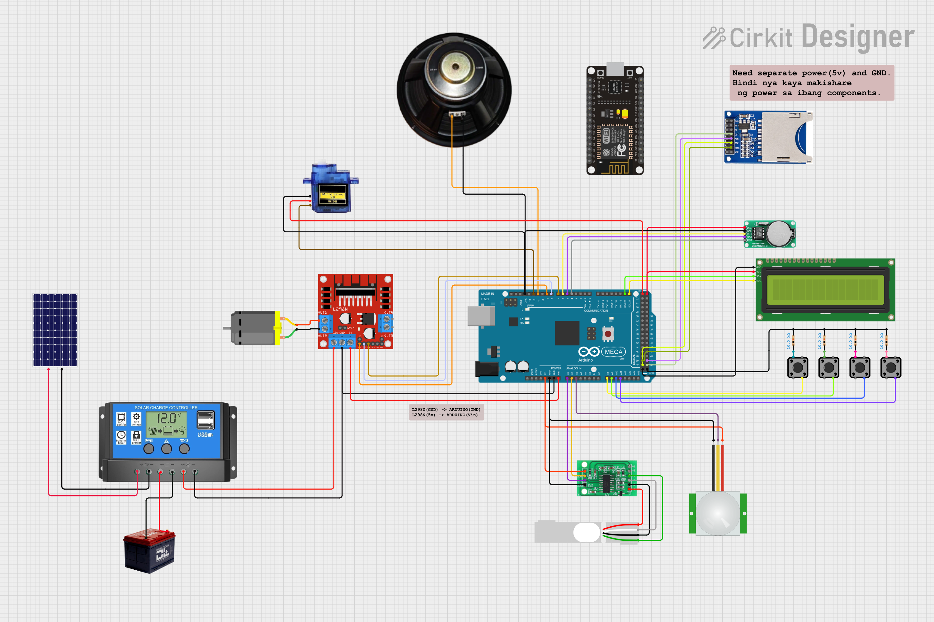
Circuit Documentation
Summary
The circuit in question appears to be a multifunctional system incorporating an Arduino Mega 2560 as the central processing unit. It interfaces with a variety of sensors, actuators, and modules, including a PIR sensor for motion detection, an HX711 load cell interface, a DS1302 real-time clock, an SD card reader for data logging, a speaker, a DC motor with an L298N driver, tactile switches, resistors, an I2C LCD for display, and a power management system consisting of a solar panel, a solar charge controller, and a 12V battery. The circuit is designed to perform tasks that likely involve data acquisition, motion sensing, weight measurement, timekeeping, data storage, and motor control, with user inputs and feedback provided via the switches and LCD.
Component List
Microcontroller
- Arduino Mega 2560: A microcontroller board based on the ATmega2560 with numerous digital and analog I/O pins.
Sensors and Modules
- DS1302 RTC: A real-time clock module for timekeeping.
- SD-CARD-READER-2PINS: An SD card module for data logging and storage.
- PIR sensor: A motion sensor that detects changes in infrared levels caused by movement.
- HX711 - Bridge Sensor Interface: An ADC converter designed for load cells and bridge sensors.
- Load Cell - Red/white/black/green: A weight sensor that measures force or load.
Actuators
- DC Motor: An electric motor that converts electrical energy into mechanical rotation.
- Micro servo 9G: A small servo motor for precise angular movement.
- Speaker: An audio output device to provide sound feedback.
Power Management
- Solar panel: A photovoltaic panel that converts sunlight into electrical energy.
- Battery 12v: A 12V battery that stores electrical energy.
- Solar Charge Controller: A device that controls the charging of the battery from the solar panel and provides power to the load.
Motor Driver
- L298N DC motor driver: A motor driver module that controls the direction and speed of DC motors.
Display
- 16x2 I2C LCD: A 16-character by 2-line liquid crystal display with an I2C interface.
User Interface
- Tactile Switch Buttons - 12mm Square: Push-button switches for user input.
Passive Components
- Resistor: A passive two-terminal electrical component that implements electrical resistance as a circuit element.
Miscellaneous
- Speaker: An audio output device.
- Comment: A non-electrical component used for annotations in the circuit design.
Wiring Details
Arduino Mega 2560
- 5V: Powers the PIR sensor, HX711, and 16x2 I2C LCD.
- GND: Common ground for PIR sensor, HX711, L298N motor driver, Speaker, Micro servo 9G, DS1302 RTC, and 16x2 I2C LCD.
- VIN: Connected to the L298N motor driver's 5V input.
- A0: Receives data from the HX711's DATA (OUT) pin.
- A1: Connected to the HX711's SCK - CLOCK (IN) pin.
- A2: Connected to the PIR sensor's SIG pin.
- A8, A9, A10, A11: Connected to tactile switches through resistors.
- D21/SCL, D20/SDA: I2C communication with the 16x2 I2C LCD.
- D4, D5, D6: Connected to the DS1302 RTC's RST, DATA, and CLK pins respectively.
- D7, D8: Control signals for the L298N motor driver's IN2 and IN1 pins.
- D9: PWM control for the L298N motor driver's ENA pin.
- D11: PWM signal to the Speaker.
- D12: PWM signal to the Micro servo 9G.
- D52, D50, D53, D51: SPI communication with the SD card reader's SCK, MISO, CS, and MOSI pins respectively.
DS1302 RTC
- VCC: Powered by the Arduino's 5V output.
- GND: Connected to the common ground.
SD-CARD-READER-2PINS
- 3.3V, 5V: Power supply (specific voltage not indicated in the net list).
- GND: Connected to the common ground.
- CS, MOSI, SCK, MISO: SPI communication with the Arduino Mega 2560.
PIR sensor
- VDD: Powered by the Arduino's 5V output.
- GND: Connected to the common ground.
- SIG: Signal output connected to the Arduino's A2 pin.
HX711 - Bridge Sensor Interface
- 3.3/3.5V Supply: Powered by the Arduino's 5V output.
- GND - GROUND: Connected to the common ground.
- DATA (OUT): Data output connected to the Arduino's A0 pin.
- SCK - CLOCK (IN): Clock input connected to the Arduino's A1 pin.
- E+, A-, E-, A+: Connected to the corresponding pins of the Load Cell.
Load Cell - Red/white/black/green
- E+, A-, E-, A+: Connected to the corresponding pins of the HX711 interface.
DC Motor
- pin 1, pin 2: Connected to the L298N motor driver's OUT2 and OUT1 pins.
L298N DC motor driver
- GND: Connected to the common ground.
- 5V: Powered by the Arduino's VIN pin.
- 12V: Powered by the Solar Charge Controller's Load + pin.
- OUT1, OUT2: Connected to the DC Motor.
- IN1, IN2, ENA: Control signals from the Arduino Mega 2560.
Solar panel
- +, -: Connected to the Solar Charge Controller's Solar Cell + and - pins.
Battery 12v
- +, -: Connected to the Solar Charge Controller's Battery + and - pins.
Solar Charge Controller
- Solar Cell +, -, Battery +, -, Load +, -: Interfacing between the solar panel, battery, and the L298N motor driver.
Tactile Switch Buttons - 12mm Square
- 1: Connected to one end of the resistors.
- 4: Connected to the Arduino's A8, A9, A10, A11 pins.
Resistor
- pin1: Connected to the tactile switches.
- pin2: Connected to the common ground.
16x2 I2C LCD
- GND: Connected to the common ground.
- VCC: Powered by the Arduino's 5V output.
- SDA, SCL: I2C communication with the Arduino Mega 2560.
Micro servo 9G
- GND: Connected to the common ground.
- +5V: Powered by the Arduino's 5V output.
- PWM: Control signal from the Arduino's D12 pin.
Documented Code
Arduino Mega 2560 - sketch.ino
void setup() {
  // put your setup code here, to run once:

}

void loop() {
  // put your main code here, to run repeatedly:

}
Arduino Mega 2560 - documentation.txt
(No additional documentation provided for the code)
(Note: The code provided is a template and does not contain any functional implementation. It will need to be populated with the logic required to control and interact with the connected components based on the specific requirements of the circuit's intended operation.)