
ESP32-Based Smart Alarm System with GPS and GSM Connectivity
View and Edit Project In Cirkit Designer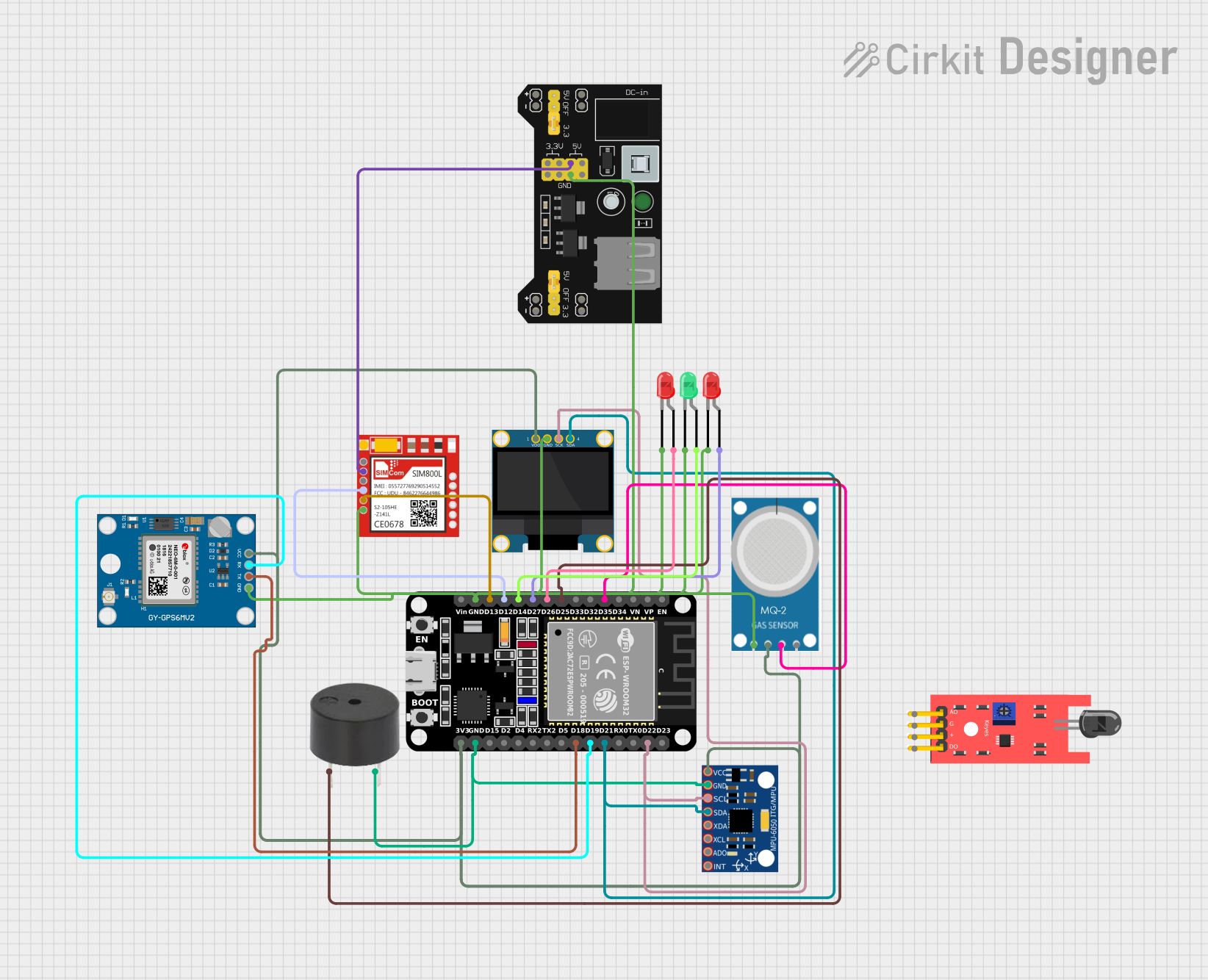
Circuit Documentation
Summary
This circuit is designed to monitor environmental conditions using various sensors and provide alerts through visual and auditory signals. It includes an ESP32 microcontroller, an MPU-6050 accelerometer and gyroscope, an MQ-2 gas sensor, a KY-026 flame sensor, a buzzer, an OLED display, LEDs, a GPS module, and a GSM module. The ESP32 collects data from the sensors, processes it, and triggers alarms if necessary. It also displays the status on the OLED screen and sends notifications via SMS and email.
Component List
ESP32 (30 pin)
- Description: A powerful microcontroller with built-in Wi-Fi and Bluetooth capabilities.
- Pins: EN, VP, VN, D34, D35, D32, D33, D25, D26, D27, D14, D12, D13, GND, Vin, D23, D22, TX0, RX0, D21, D19, D18, D5, TX2, RX2, D4, D2, D15, 3V3
MPU-6050
- Description: A 6-axis accelerometer and gyroscope sensor.
- Pins: VCC, GND, SCL, SDA, XDA, XCL, AD0, INT
MQ-2
- Description: A gas sensor that detects smoke, propane, methane, and other combustible gases.
- Pins: GND, VCC, ANALOG, Digital
KY-026 Flame Sensor
- Description: A sensor that detects flame and fire.
- Pins: A0, GND, VCC, D0
Buzzer
- Description: An electronic device that produces a sound when activated.
- Pins: PIN, GND
OLED 128x64 I2C Monochrome Display VDD-GND
- Description: A small OLED display for visual output.
- Pins: VDD, GND, SCK, SDA
LED: Two Pin (green)
- Description: A green LED for visual indication.
- Pins: cathode, anode
Neo 6M GPS Module
- Description: A GPS module for location tracking.
- Pins: GND, TX, RX, VCC
LED: Two Pin (red)
- Description: A red LED for visual indication.
- Pins: cathode, anode
Sim800l
- Description: A GSM module for sending SMS.
- Pins: NET, RST, VCC, RXD, TXD, GND
MB102 Breadboard Power Supply Module 3.3V/5V
- Description: A power supply module for providing 3.3V and 5V outputs.
- Pins: VCC, GND, 3.3V, 5V
Wiring Details
ESP32 (30 pin)
- D35: Connected to MQ-2 (ANALOG)
- D25: Connected to Buzzer (PIN)
- D26: Connected to Red LED (anode)
- D27: Connected to Red LED (anode)
- D14: Connected to Green LED (anode)
- D12: Connected to Sim800l (RXD)
- D13: Connected to Sim800l (TXD)
- D22: Connected to MPU-6050 (SCL) and OLED Display (SCK)
- D21: Connected to MPU-6050 (SDA) and OLED Display (SDA)
- D19: Connected to Neo 6M GPS Module (RX)
- D18: Connected to Neo 6M GPS Module (TX)
- GND: Connected to common ground with multiple components
- 3V3: Connected to VCC of MQ-2, MPU-6050, OLED Display, and Neo 6M GPS Module
MPU-6050
- SCL: Connected to ESP32 (D22) and OLED Display (SCK)
- SDA: Connected to ESP32 (D21) and OLED Display (SDA)
- GND: Connected to common ground
- VCC: Connected to ESP32 (3V3)
MQ-2
- ANALOG: Connected to ESP32 (D35)
- GND: Connected to common ground
- VCC: Connected to ESP32 (3V3)
KY-026 Flame Sensor
- D0: Not connected in the provided net list
- GND: Not connected in the provided net list
- VCC: Not connected in the provided net list
Buzzer
- PIN: Connected to ESP32 (D25)
- GND: Connected to common ground
OLED 128x64 I2C Monochrome Display VDD-GND
- SCK: Connected to ESP32 (D22) and MPU-6050 (SCL)
- SDA: Connected to ESP32 (D21) and MPU-6050 (SDA)
- GND: Connected to common ground
- VDD: Connected to ESP32 (3V3)
LED: Two Pin (green)
- anode: Connected to ESP32 (D14)
- cathode: Connected to common ground
Neo 6M GPS Module
- RX: Connected to ESP32 (D19)
- TX: Connected to ESP32 (D18)
- GND: Connected to common ground
- VCC: Connected to ESP32 (3V3)
LED: Two Pin (red)
- anode: Connected to ESP32 (D26) and ESP32 (D27)
- cathode: Connected to common ground
Sim800l
- RXD: Connected to ESP32 (D12)
- TXD: Connected to ESP32 (D13)
- GND: Connected to common ground
- VCC: Connected to MB102 Breadboard Power Supply Module (5V)
MB102 Breadboard Power Supply Module 3.3V/5V
- GND: Connected to common ground
- 5V: Connected to Sim800l (VCC)
Code Documentation
#include <Wire.h>
#include <Adafruit_GFX.h>
#include <Adafruit_SSD1306.h>
#include <TinyGPS++.h>
#include <SoftwareSerial.h>
#include <WiFi.h>
#include <SMTPClient.h>

// Define pins
#define MPU_SCL 22
#define MPU_SDA 21
#define MQ2_ANALOG 35
#define FLAME_SENSOR_PIN 19
#define BUZZER_PIN 25
#define RED_LED1_PIN 26
#define RED_LED2_PIN 27
#define GREEN_LED_PIN 14
#define GSM_RX_PIN 16
#define GSM_TX_PIN 17
#define GPS_RX_PIN 18
#define GPS_TX_PIN 19

// Initialize components
Adafruit_SSD1306 display(128, 64, &Wire);
TinyGPSPlus gps;
SoftwareSerial gsmSerial(GSM_RX_PIN, GSM_TX_PIN);
SoftwareSerial gpsSerial(GPS_RX_PIN, GPS_TX_PIN);

void setup() {
  // Initialize Serial
  Serial.begin(115200);
  gsmSerial.begin(9600);
  gpsSerial.begin(9600);

  // Initialize I2C
  Wire.begin(MPU_SDA, MPU_SCL);

  // Initialize OLED
  if (!display.begin(SSD1306_I2C_ADDRESS, OLED_RESET)) {
    Serial.println(F("SSD1306 allocation failed"));
    for (;;);
  }
  display.display();
  delay(2000);
  display.clearDisplay();

  // Initialize pins
  pinMode(MQ2_ANALOG, INPUT);
  pinMode(FLAME_SENSOR_PIN, INPUT);
  pinMode(BUZZER_PIN, OUTPUT);
  pinMode(RED_LED1_PIN, OUTPUT);
  pinMode(RED_LED2_PIN, OUTPUT);
  pinMode(GREEN_LED_PIN, OUTPUT);

  // Initialize Wi-Fi
  WiFi.begin("your-SSID", "your-PASSWORD");
  while (WiFi.status() != WL_CONNECTED) {
    delay(1000);
    Serial.println("Connecting to WiFi...");
  }
  Serial.println("Connected to WiFi");
}

void loop() {
  // Read sensors
  int mq2Value = analogRead(MQ2_ANALOG);
  int flameValue = digitalRead(FLAME_SENSOR_PIN);

  // Check for earthquake (MPU-6050)
  // Add your MPU-6050 reading and processing code here

  // Check for smoke
  if (mq2Value > SMOKE_THRESHOLD) {
    triggerAlarm("Smoke detected!");
  }

  // Check for flame
  if (flameValue == HIGH) {
    triggerAlarm("Flame detected!");
  }

  // Read GPS data
  while (gpsSerial.available() > 0) {
    gps.encode(gpsSerial.read());
  }

  // Display status on OLED
  display.clearDisplay();
  display.setCursor(0, 0