Cirkit Designer
Your all-in-one circuit design IDE
Home /
Project Documentation
Arduino UNO Based IR Sensor Controlled LED
Circuit Documentation
Summary of the Circuit
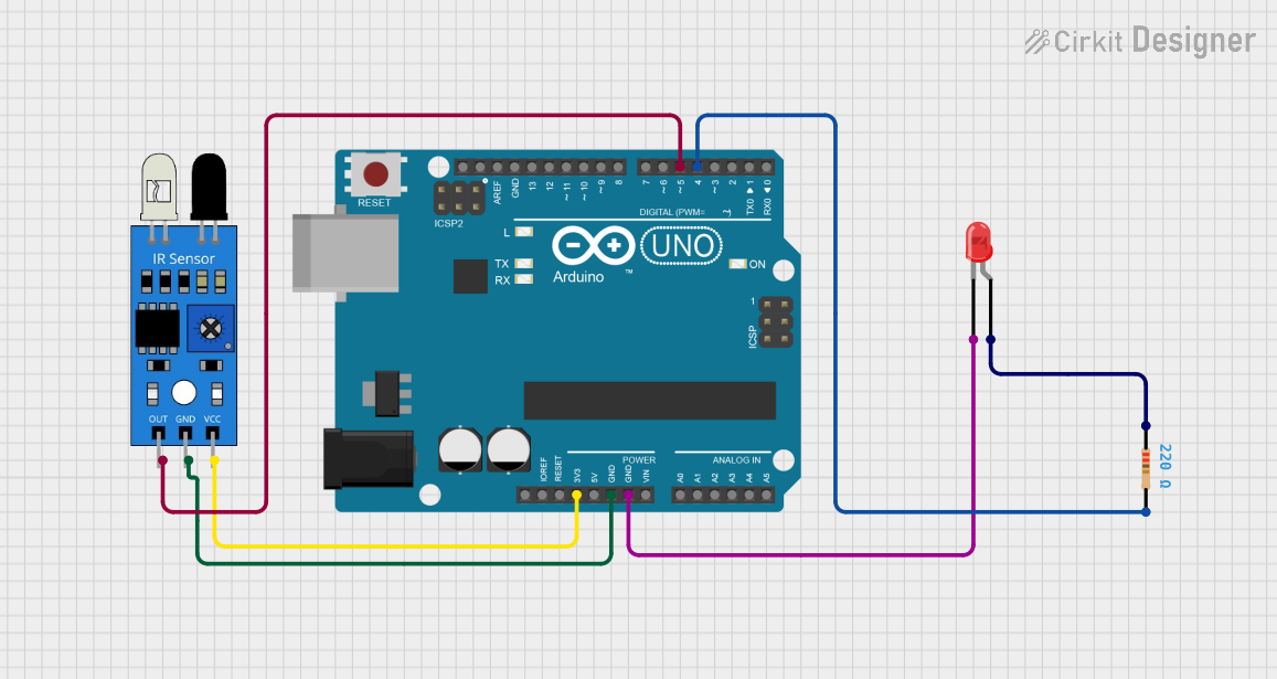
This circuit is designed to interface an IR sensor with an Arduino UNO microcontroller and includes an LED indicator. The Arduino UNO is used as the central processing unit to read the output from the IR sensor and control the LED based on the sensor's output. The LED serves as a visual indicator and is connected through a 220 Ohm resistor to limit the current.
Component List
Arduino UNO
- Description: A microcontroller board based on the ATmega328P.
- Purpose: Acts as the central processing unit for the circuit, reading sensor data and controlling the LED.
IR Sensor
- Description: An infrared sensor capable of detecting IR signals.
- Purpose: Provides input to the Arduino based on IR signal detection.
LED: Two Pin (Red)
- Description: A basic red light-emitting diode.
- Purpose: Serves as a visual indicator when powered.
Resistor
- Description: A passive two-terminal electrical component that implements electrical resistance.
- Value: 220 Ohms
- Purpose: Limits the current flowing through the LED to prevent damage.
Wiring Details
Arduino UNO
- 3.3V connected to IR Sensor VCC
- GND connected to:
- IR Sensor GND
- LED Cathode (through the resistor)
- D5 connected to IR Sensor OUT
- D4 connected to Resistor Pin2
IR Sensor
- VCC connected to Arduino UNO 3.3V
- GND connected to Arduino UNO GND
- OUT connected to Arduino UNO D5
LED: Two Pin (Red)
- Cathode connected to Arduino UNO GND (through the resistor)
- Anode connected to Resistor Pin1
Resistor
- Pin1 connected to LED Anode
- Pin2 connected to Arduino UNO D4
Documented Code
Arduino UNO Code (sketch.ino)
void setup() {
  // put your setup code here, to run once:

}

void loop() {
  // put your main code here, to run repeatedly:

}
Note: The provided code is a template and does not contain any functional code to interact with the IR sensor or control the LED. The user is expected to fill in the setup and loop functions with the appropriate logic for the intended behavior of the circuit.