
Arduino Mega 2560-Based Motor Control System with Dual Micro Switches and Potentiometer
View and Edit Project In Cirkit Designer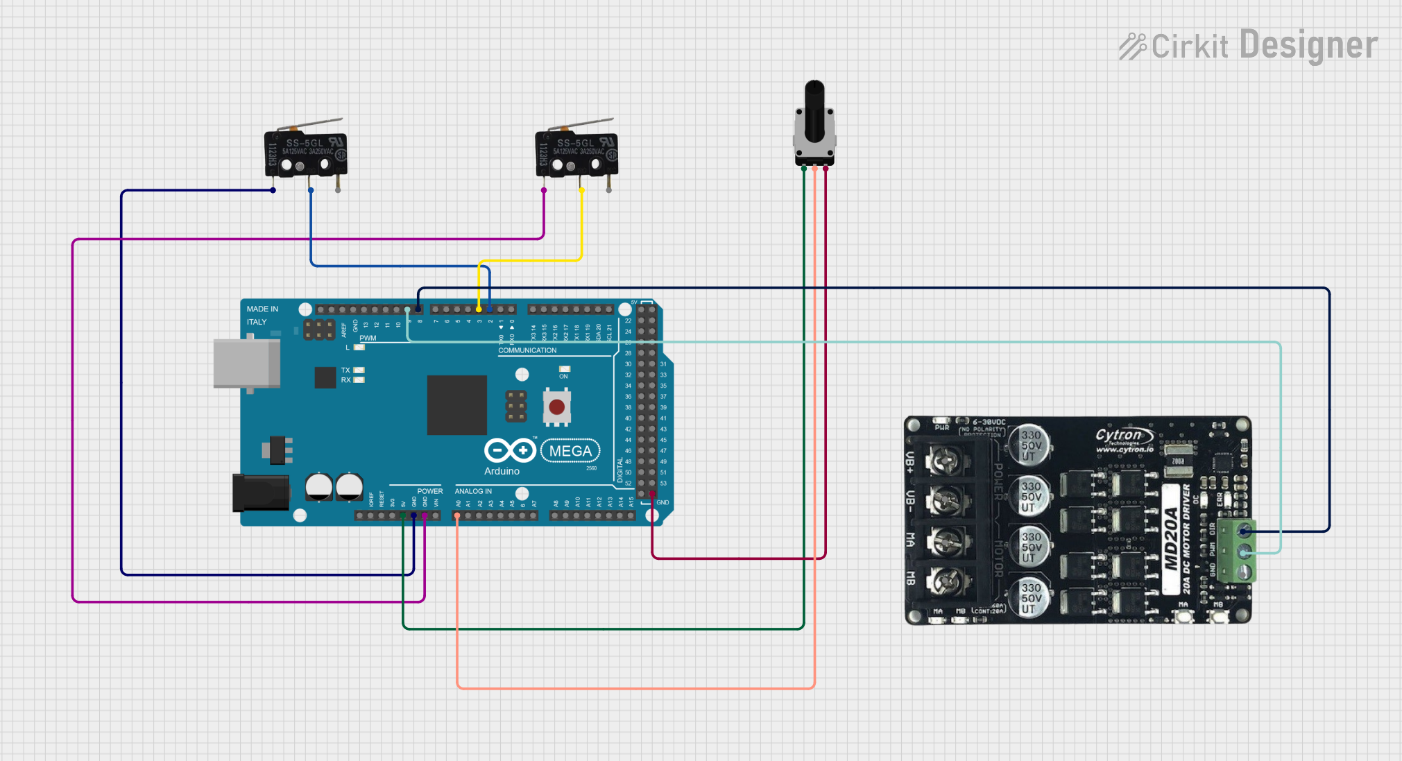
Circuit Documentation
Summary
This document provides a detailed overview of a circuit that includes an Arduino Mega 2560 microcontroller, two micro switches, a rotary potentiometer, and an MD20 Cytron motor driver. The circuit is designed to interface with various input and output components, allowing for control and monitoring through the Arduino Mega 2560.
Component List
Arduino Mega 2560
- Description: A microcontroller board based on the ATmega2560.
- Pins: IOREF, RESET, 3V3, 5V, GND, VIN, A0-A15, D0-D53, AREF, SDA, SCL
Micro Switch (1)
- Description: A small switch used for detecting physical interactions.
- Pins: COM, NO, NC
Micro Switch (2)
- Description: A small switch used for detecting physical interactions.
- Pins: COM, NO, NC
Rotary Potentiometer
- Description: A variable resistor used to adjust voltage levels.
- Pins: leg1, wiper, leg2
- Properties:
- Resistance: 10,000 Ohms
MD20 Cytron Motor Driver
- Description: A motor driver used to control the speed and direction of a motor.
- Pins: VB+, VB-, MA, MB, GND, PWM, DIR
Wiring Details
Arduino Mega 2560
- 5V connected to Rotary Potentiometer leg1
- GND connected to Micro Switch (1) COM
- GND connected to Micro Switch (2) COM
- A0 connected to Rotary Potentiometer wiper
- D2 PWM connected to Micro Switch (1) NO
- D3 PWM connected to Micro Switch (2) NO
- D8 PWM connected to MD20 Cytron Motor Driver DIR
- D9 PWM connected to MD20 Cytron Motor Driver PWM
- GND connected to Rotary Potentiometer leg2
Micro Switch (1)
- COM connected to Arduino Mega 2560 GND
- NO connected to Arduino Mega 2560 D2 PWM
Micro Switch (2)
- COM connected to Arduino Mega 2560 GND
- NO connected to Arduino Mega 2560 D3 PWM
Rotary Potentiometer
- leg1 connected to Arduino Mega 2560 5V
- wiper connected to Arduino Mega 2560 A0
- leg2 connected to Arduino Mega 2560 GND
MD20 Cytron Motor Driver
- DIR connected to Arduino Mega 2560 D8 PWM
- PWM connected to Arduino Mega 2560 D9 PWM
Documented Code
Arduino Mega 2560 Code (sketch.ino)
void setup() {
  // put your setup code here, to run once:

}

void loop() {
  // put your main code here, to run repeatedly:

}
Additional Documentation (documentation.txt)
This document provides a comprehensive overview of the circuit, including a summary, component list, wiring details, and documented code. The Arduino Mega 2560 serves as the central microcontroller, interfacing with various input and output components to achieve the desired functionality.