Cirkit Designer
Your all-in-one circuit design IDE
Home /
Project Documentation
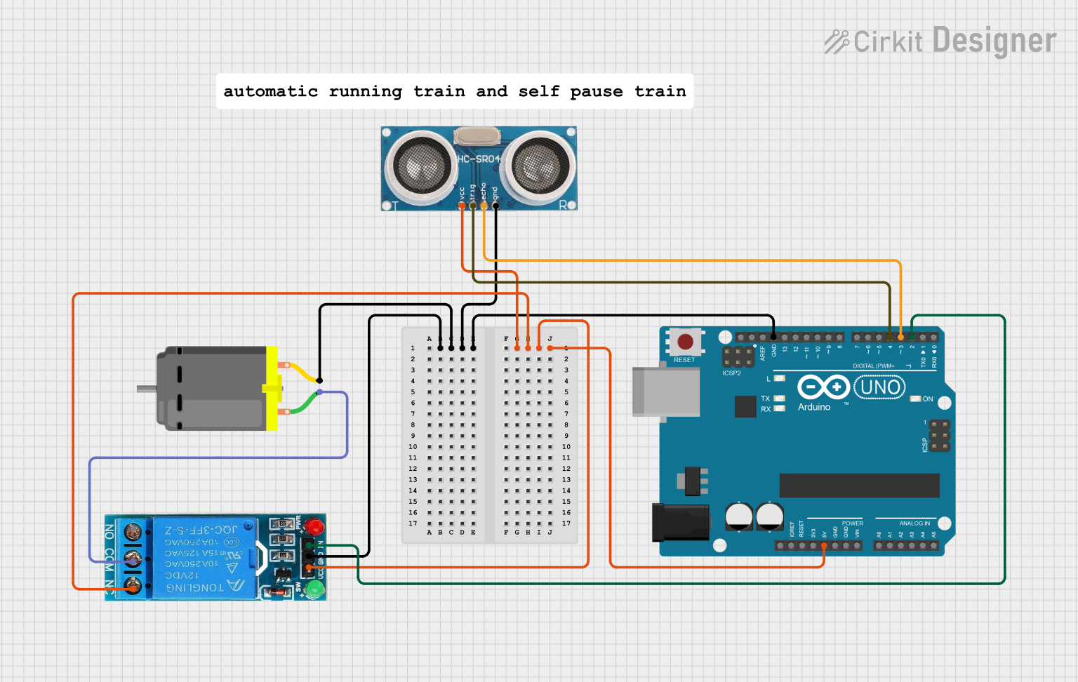
Arduino-Controlled Ultrasonic Sensor with Relay-Operated DC Motor
Circuit Documentation
Summary
This circuit integrates an ultrasonic sensor, an Arduino UNO microcontroller, a 12V single-channel relay, and a DC motor to form a control system. The ultrasonic sensor is likely used for distance measurement, while the Arduino UNO serves as the central processing unit. The relay acts as an electrically operated switch to control the DC motor, which is the actuator of the system.
Component List
Ultrasonic Sensor
- Pins: +VCC, Trigger, Echo, GND
- Description: A sensor that measures distance by emitting ultrasonic waves and measuring the time taken for the echo to return.
Arduino UNO
- Pins: UNUSED, IOREF, Reset, 3.3V, 5V, GND, Vin, A0-A5, SCL, SDA, AREF, D0-D13
- Description: A microcontroller board based on the ATmega328P, widely used for building digital devices and interactive objects that can sense and control objects in the physical world.
12V Single Channel Relay
- Pins: NC, COM, NO, IN, GND, VCC
- Description: An electromechanical switch that allows a low-power circuit to switch a relatively high current on and off.
DC Motor
- Pins: pin 1, pin 2
- Description: An electric motor that runs on direct current electricity, used to convert electrical energy into mechanical motion.
Comment
- Pins: None
- Description: This component seems to be a placeholder or a note and does not have a physical representation in the circuit.
Wiring Details
Ultrasonic Sensor
- +VCC: Connected to Arduino UNO 5V
- Trigger: Connected to Arduino UNO D4
- Echo: Connected to Arduino UNO D3
- GND: Common ground with Arduino UNO, DC Motor, and 12V Single Channel Relay
Arduino UNO
- 5V: Provides power to the Ultrasonic Sensor
- D4: Sends trigger signal to the Ultrasonic Sensor
- D3: Receives echo signal from the Ultrasonic Sensor
- D2: Controls the 12V Single Channel Relay
- GND: Common ground with Ultrasonic Sensor, DC Motor, and 12V Single Channel Relay
12V Single Channel Relay
- NC: Not connected in this circuit
- COM: Connected to DC Motor pin 1
- NO: Not used in this circuit
- IN: Controlled by Arduino UNO D2
- GND: Common ground with Arduino UNO, Ultrasonic Sensor, and DC Motor
- VCC: Powered by Arduino UNO 5V
DC Motor
- pin 1: Connected to 12V Single Channel Relay COM
- pin 2: Common ground with Arduino UNO, Ultrasonic Sensor, and 12V Single Channel Relay
Documented Code
Arduino UNO Code (sketch.ino)
void setup() {
  // put your setup code here, to run once:

}

void loop() {
  // put your main code here, to run repeatedly:

}
Additional Notes (documentation.txt)
No additional code documentation provided.