
Arduino Mega 2560 Based Weather Monitoring and Alarm System with I2C LCD, RTC, and Sensors
View and Edit Project In Cirkit Designer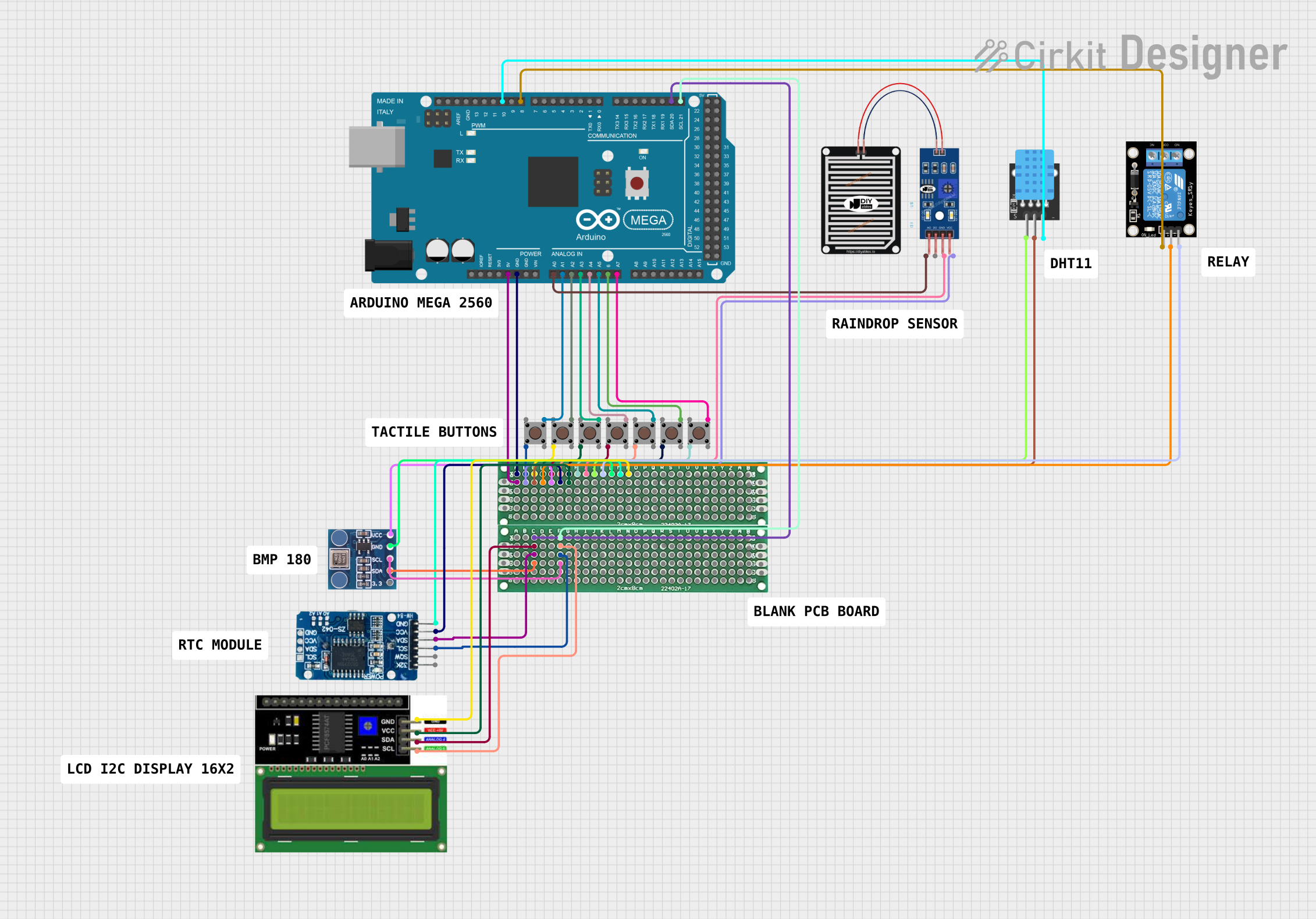
Circuit Documentation
Summary
The circuit in question is a multifunctional system that incorporates various sensors, a display, a real-time clock (RTC), and a microcontroller to manage inputs and outputs. The primary controller is an Arduino Mega 2560, which interfaces with an LCD I2C display, RTC DS3231, a rain sensor, a DHT11 temperature and humidity sensor, a BMP180 pressure sensor, a relay module, and multiple pushbuttons. The circuit is designed to monitor environmental conditions and control external devices based on sensor readings and user inputs.
Component List
Arduino Mega 2560
- Description: A microcontroller board based on the ATmega2560.
- Purpose: Acts as the central processing unit for the circuit, reading sensor data, controlling the display, and managing user inputs.
LCD I2C Display
- Description: A liquid crystal display with an I2C interface.
- Purpose: Displays real-time data, alarm settings, and other user interface elements.
RTC DS3231
- Description: A real-time clock module for precise timekeeping.
- Purpose: Provides accurate time and date for the system, used for scheduling and alarm functions.
Rain Sensor
- Description: A sensor that detects rainwater.
- Purpose: Monitors environmental conditions to influence system behavior.
DHT11
- Description: A sensor for measuring temperature and humidity.
- Purpose: Provides temperature and humidity readings for display and decision-making processes.
Relay Module 1 Channel
- Description: An electrically operated switch.
- Purpose: Controls high-power devices such as pumps or lights based on the microcontroller's output.
Pushbuttons
- Description: Simple tactile switches.
- Purpose: Allows user interaction with the system for settings adjustments and manual control.
BMP180
- Description: A digital barometric pressure sensor.
- Purpose: Measures atmospheric pressure for display and potentially for weather prediction.
2cmx8cm PCBs
- Description: Printed circuit boards used for mounting and connecting components.
- Purpose: Provides a physical platform for the circuit and facilitates electrical connections.
Comments
- Description: Text placeholders for notes or labels within the circuit design.
- Purpose: Used for documentation and clarification within the circuit design, not a physical component.
Wiring Details
Arduino Mega 2560
- 5V and GND are used to power the circuit.
- Analog pins A0 to A7 are connected to the rain sensor and pushbuttons.
- Digital pins D8 and D10 are connected to the relay module and DHT11 sensor.
- I2C pins SDA and SCL are connected to the I2C bus on the PCB for communication with the LCD display, RTC, and BMP180 sensor.
LCD I2C Display
- GND and VCC are connected to the power supply.
- SDA and SCL are connected to the I2C bus for communication with the Arduino Mega 2560.
RTC DS3231
- VCC and GND provide power to the module.
- SDA and SCL are connected to the I2C bus for timekeeping data exchange with the Arduino Mega 2560.
Rain Sensor
- AO (Analog Output) is connected to the Arduino's A0 pin for rain detection.
- VCC and GRD (Ground) are connected to the power supply.
DHT11
- Pin S is connected to the Arduino's D10 pin for data communication.
- 5V and GND provide power to the sensor.
Relay Module 1 Channel
- S (Signal) is connected to the Arduino's D8 pin for control.
- 5V and GND are connected to the power supply.
Pushbuttons
- One side of each pushbutton is connected to the Arduino's analog pins A1 to A7.
- The other side of each pushbutton is connected to the power supply.
BMP180
- VCC and GND provide power to the sensor.
- SDA and SCL are connected to the I2C bus for pressure data exchange with the Arduino Mega 2560.
Documented Code
The code for the Arduino Mega 2560 is written in C++ and utilizes several libraries for interfacing with the hardware components. The code manages sensor readings, user inputs, displays information on the LCD, and controls the relay based on the logic defined within the program.
#include <Wire.h>
#include <Adafruit_BMP085.h>
#include <LiquidCrystal_I2C.h>
#include <RTClib.h>
#include <EEPROM.h>
#include <Countimer.h>
#include <SimpleDHT.h>

// Define pin connections & constants
#define bt_select A1
#define bt_data A2
#define bt_up A3
#define bt_down A4
#define bt_manual_start A5
#define bt_manual_stop A6
#define bt_pumpstartwithtimer A7
#define buzzer 8
#define EEPROM_ADDR_ALARM_HH 1
#define EEPROM_ADDR_ALARM_MM 2
#define EEPROM_ADDR_ALARM_SS 3
#define EEPROM_ADDR_MODE 4
#define EEPROM_ADDR_STOP 50
#define seconds 6
#define minutes 7
#define hours 8

// Initialize objects for sensors and display
Countimer tdown;
LiquidCrystal_I2C lcd(0x27, 16, 2);
Adafruit_BMP085 bmp;
RTC_DS3231 rtc;
DateTime now;

// Variables for time, date, and alarm settings
int hh = 0, mm = 0, ss = 0, dd = 0, bb = 0, yy = 0;
int set_day = 1;
String Day = "  ";
int AlarmHH = 21, AlarmMM = 22, AlarmSS = 23;
int setMode = 0, setAlarm = 0, alarmMode = 0, setrunTimer = 0, setselect = 0;
int stop = 0, mode = 0, flag = 0;
bool alarmActive = false;
unsigned long buzzerStartTime = 0;
bool timerWaitingToStart = true;
bool showTemperatureHumidity = false;
bool alarmWorking = false;
bool skipNextAlarm = false;
bool delayalarm = false;
bool startdelay = false;
const int SENSOR_PIN = A0;
const int SENSOR_THRESHOLD = 500;
const unsigned long ALARM_WORKING_TIMEOUT = 10000;
const unsigned long ALARM_NOT_WORKING_TIMEOUT = 20000;
unsigned long alarmStateChangeTime = 0;
unsigned long startTime = 0;
const unsigned long conditionDuration = 5000;
unsigned long delayStartTime = 0;
const unsigned long DELAY_DURATION = 7000;
int time_s = 0;
int time_m = 0;
int time_h = 0;
int pump = 0;
int flag1 = 0, flag2 = 0;
int pinDHT11 = 10;
SimpleDHT11 dht11(pinDHT11);

// Custom character for the LCD display
byte bell_symbol[8] = {
  B00100,
  B01110,
  B01110,
  B01110,
  B01110,
  B11111,
  B01000,
  B00100
};

// Function prototypes
void ReadEeprom();
void WriteEeprom();
void printTwoDigits(int number);
void printFourDigits(int number);
void setTimer();
void setupClock();
void blinking();

void print_time();
void tdownComplete();
void setup1();
void eeprom_read();
void runTimer();
void setrunTimerrun();
void humidity();

// Setup function runs once at startup
void setup() {
  // Initialize serial communication and I2C interface
  Serial.begin(9600);
  Wire.begin();
  rtc.begin();

  // Setup pin modes for buttons and buzzer
  pinMode(bt_up, INPUT_PULLUP);
  pinMode(bt_down, INPUT_PULLUP);
  pinMode(bt_manual_start, INPUT_PULLUP);
  pinMode(bt_manual_stop, INPUT_PULLUP);
  pinMode(bt_data, INPUT_PULLUP);
  pinMode(bt_pumpstartwithtimer, INPUT_PULLUP);
  pinMode(bt_select, INPUT_PULLUP);
  pinMode(buzzer, OUTPUT);

  // Create custom LCD character
  lcd.createChar(2, bell_symbol);

  // Initialize the LCD and display startup message
  lcd.begin();
  lcd.setCursor(0, 0);
  lcd.print(" Real Time Clock ");
  lcd.setCursor(0, 1);
  lcd.print("   With Alarm ");
  tdown.setInterval(print_time, 999);
  eeprom_read();
  delay(2000);
  lcd.clear();

  // Check if the system was stopped and reset EEPROM if necessary
  stop = EEPROM.read(EEPROM_ADDR_STOP);
  if (stop != 0) {
    WriteEeprom();
  }
  EEPROM.write(EEPROM_ADDR_STOP, 0);

  // Read alarm settings and mode from EEPROM
  AlarmHH = EEPROM.read(EEPROM_ADDR_ALARM_HH);
  AlarmMM = EEPROM.read(EEPROM_ADDR_ALARM_MM);
  AlarmSS = EEPROM.read(EEPROM_ADDR_ALARM_SS);
  mode = EEPROM.read(EEPROM_ADDR_MODE);

  // Initialize the BMP180 sensor
  if (!bmp.begin()) {
    Serial.println("Could not find a valid BMP085 sensor, check wiring!");
    while (1) {}
  }
}

// Placeholder for tdownComplete function
void tdownComplete() {
  Serial.print("ok");
}

// Main loop function runs repeatedly
void loop() {
  // Placeholder for main loop code
}

// Additional functions and logic for handling sensor readings, user inputs, and display updates