
Circuit Documentation
Summary
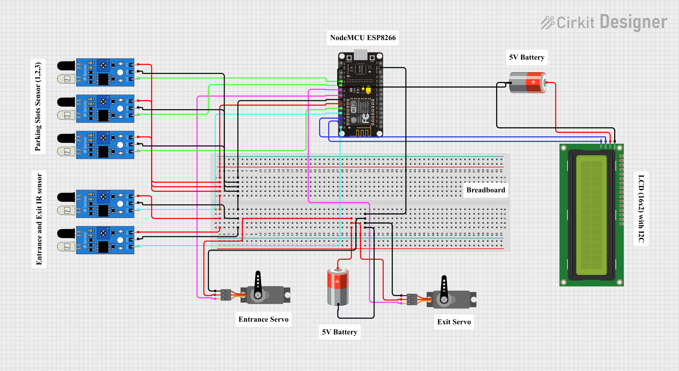
This document provides a detailed overview of a circuit that includes an ESP8266 NodeMCU microcontroller, multiple IR sensors, servos, a 16x2 I2C LCD, and power sources. The circuit is designed to interface with various sensors and actuators, with the ESP8266 NodeMCU serving as the central control unit.
Component List
ESP8266 NodeMCU
- Description: A low-cost Wi-Fi microcontroller with GPIO, ADC, and PWM capabilities.
- Pins: D0, D1, D2, D3, D4, 3V3, GND, D5, D6, D7, D8, RX, TX, A0, RSV, SD3, SD2, SD1, CMD, SD0, CLK, EN, RST, VIN
IR Sensor
- Description: Infrared sensor used for object detection.
- Pins: out, gnd, vcc
Servo
- Description: A small actuator used for precise control of angular position.
- Pins: GND, VCC, PWM
16x2 I2C LCD
- Description: A 16x2 character LCD display with I2C interface.
- Pins: GND, VCC, SDA, SCL
5V Battery
- Description: Power source providing 5V.
- Pins: +, -
Wiring Details
ESP8266 NodeMCU
- 3V3: Connected to the VCC pins of all IR sensors.
- GND: Connected to the GND pins of all IR sensors, the GND pin of the 16x2 I2C LCD, and the negative terminal of the 5V battery.
- D0: Connected to the out pin of the first IR sensor.
- D1: Connected to the SCL pin of the 16x2 I2C LCD.
- D2: Connected to the SDA pin of the 16x2 I2C LCD.
- D3: Connected to the out pin of the second IR sensor.
- D4: Connected to the out pin of the third IR sensor.
- D5: Connected to the PWM pin of the first servo.
- D6: Connected to the PWM pin of the second servo.
- D7: Connected to the out pin of the fourth IR sensor.
- D8: Connected to the out pin of the fifth IR sensor.
IR Sensor
- VCC: Connected to the 3V3 pin of the ESP8266 NodeMCU.
- GND: Connected to the GND pin of the ESP8266 NodeMCU.
- out:
- First IR sensor: Connected to D0 of the ESP8266 NodeMCU.
- Second IR sensor: Connected to D3 of the ESP8266 NodeMCU.
- Third IR sensor: Connected to D4 of the ESP8266 NodeMCU.
- Fourth IR sensor: Connected to D7 of the ESP8266 NodeMCU.
- Fifth IR sensor: Connected to D8 of the ESP8266 NodeMCU.
Servo
- VCC: Connected to the positive terminal of the 5V battery.
- GND: Connected to the negative terminal of the 5V battery.
- PWM:
- First servo: Connected to D5 of the ESP8266 NodeMCU.
- Second servo: Connected to D6 of the ESP8266 NodeMCU.
16x2 I2C LCD
- GND: Connected to the negative terminal of the 5V battery.
- VCC: Connected to the positive terminal of the 5V battery.
- SDA: Connected to D2 of the ESP8266 NodeMCU.
- SCL: Connected to D1 of the ESP8266 NodeMCU.
5V Battery
- +: Connected to the VCC pins of the servos and the 16x2 I2C LCD.
- -: Connected to the GND pins of the servos, the 16x2 I2C LCD, and the GND pin of the ESP8266 NodeMCU.
Code
No code is provided for this circuit.