
Arduino Mega 2560 Laser Diode and Photocell Array with Loudspeaker
View and Edit Project In Cirkit Designer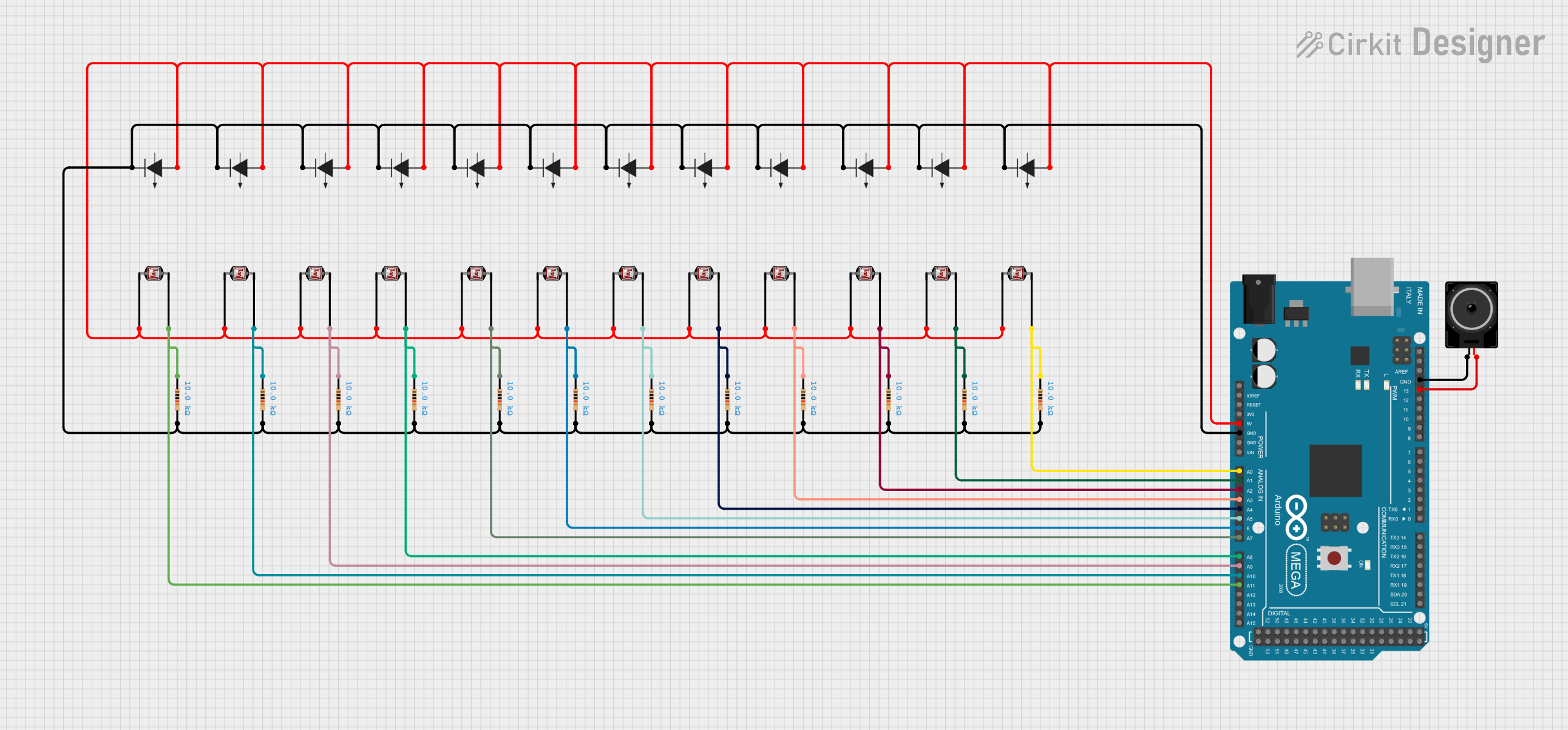
Circuit Documentation
Summary
This circuit involves an Arduino Mega 2560 microcontroller, multiple laser diodes, photocells (LDRs), resistors, and a loudspeaker. The Arduino Mega 2560 is used to control and read data from the various components. The laser diodes are connected to the photocells, which detect the presence of the laser light. The resistors are used to limit the current through the photocells. The loudspeaker is connected to the Arduino to provide audio feedback.
Component List
Arduino Mega 2560
- Description: A microcontroller board based on the ATmega2560.
- Pins: IOREF, RESET, 3V3, 5V, GND, VIN, A0-A15, D0-D53, AREF, SDA, SCL
Laser Diode
- Description: A diode that emits laser light.
- Pins: +, -
Photocell (LDR)
- Description: A light-dependent resistor that changes its resistance based on the amount of light it receives.
- Pins: pin 0, pin 1
Resistor
- Description: A passive electrical component that limits the flow of electric current.
- Pins: pin1, pin2
- Properties:
- Resistance: 10,000 Ohms
Loudspeaker
- Description: An electroacoustic transducer that produces sound in response to an electrical audio signal.
- Pins: pin1, pin2
Wiring Details
Arduino Mega 2560
- 5V:
- Connected to the + pin of multiple laser diodes.
- GND:
- Connected to the - pin of multiple laser diodes.
- Connected to pin1 of the loudspeaker.
- A0:
- Connected to pin 1 of a photocell.
- Connected to pin1 of a resistor.
- A1:
- Connected to pin 1 of a photocell.
- Connected to pin1 of a resistor.
- A2:
- Connected to pin 1 of a photocell.
- Connected to pin1 of a resistor.
- A3:
- Connected to pin 1 of a photocell.
- Connected to pin1 of a resistor.
- A4:
- Connected to pin 1 of a photocell.
- Connected to pin1 of a resistor.
- A5:
- Connected to pin 1 of a photocell.
- Connected to pin1 of a resistor.
- A6:
- Connected to pin 1 of a photocell.
- Connected to pin1 of a resistor.
- A7:
- Connected to pin 1 of a photocell.
- Connected to pin1 of a resistor.
- A8:
- Connected to pin 1 of a photocell.
- Connected to pin1 of a resistor.
- A9:
- Connected to pin 1 of a photocell.
- Connected to pin1 of a resistor.
- A10:
- Connected to pin 1 of a photocell.
- Connected to pin1 of a resistor.
- A11:
- Connected to pin 1 of a photocell.
- Connected to pin1 of a resistor.
- D13 PWM:
- Connected to pin2 of the loudspeaker.
Laser Diode
- +:
- Connected to the 5V pin of the Arduino Mega 2560.
- Connected to pin 0 of multiple photocells.
- -:
- Connected to the GND pin of the Arduino Mega 2560.
- Connected to pin2 of multiple resistors.
Photocell (LDR)
- pin 0:
- Connected to the + pin of multiple laser diodes.
- pin 1:
- Connected to A0-A11 pins of the Arduino Mega 2560.
- Connected to pin1 of multiple resistors.
Resistor
- pin1:
- Connected to pin 1 of multiple photocells.
- Connected to A0-A11 pins of the Arduino Mega 2560.
- pin2:
- Connected to the - pin of multiple laser diodes.
- Connected to the GND pin of the Arduino Mega 2560.
Loudspeaker
- pin1:
- Connected to the GND pin of the Arduino Mega 2560.
- pin2:
- Connected to the D13 PWM pin of the Arduino Mega 2560.
Code Documentation
Arduino Mega 2560 Code
sketch.ino
void setup() {
  // put your setup code here, to run once:

}

void loop() {
  // put your main code here, to run repeatedly:

}
documentation.txt