
Battery-Powered Laser Diode and Buzzer Circuit with Photocell Control
View and Edit Project In Cirkit Designer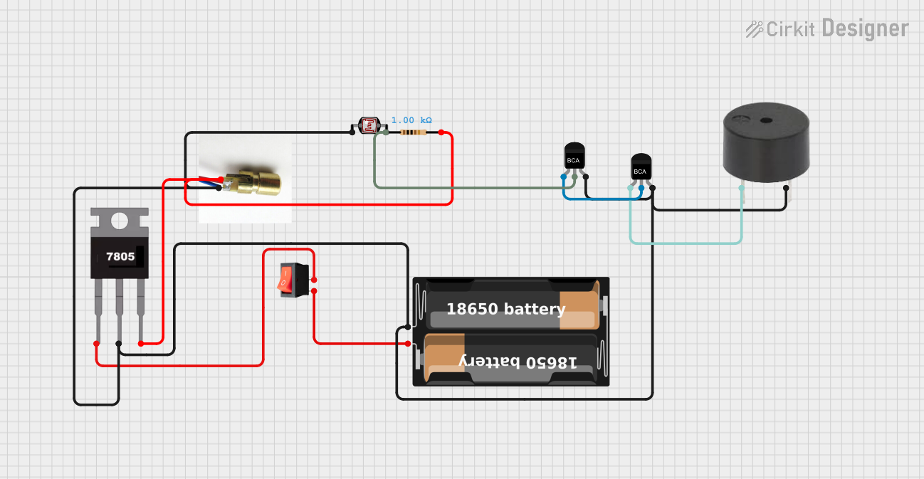
Circuit Documentation
Summary
This document provides a detailed overview of a circuit that includes a laser diode, a rocker switch, a battery case, a buzzer, two NPN transistors, a 7805 voltage regulator, a photocell (LDR), and a resistor. The circuit is designed to control the laser diode and buzzer using the transistors and other components.
Component List
Laser Diode
- Pins: negative, positive
- Description: A diode that emits laser light when current flows through it.
- Purpose in Circuit: Emits laser light when powered.
Rocker Switch
- Pins: input, output
- Description: A switch that toggles between on and off states.
- Purpose in Circuit: Controls the power supply to the circuit.
Battery Case
- Pins: +, -
- Description: Holds the batteries and provides power to the circuit.
- Purpose in Circuit: Supplies power to the circuit.
Buzzer
- Pins: PIN, GND
- Description: An audio signaling device.
- Purpose in Circuit: Emits sound when activated.
NPN Transistor (1)
- Pins: E, C, B
- Description: A type of bipolar junction transistor.
- Purpose in Circuit: Acts as a switch or amplifier.
NPN Transistor (2)
- Pins: E, C, B
- Description: A type of bipolar junction transistor.
- Purpose in Circuit: Acts as a switch or amplifier.
7805 Voltage Regulator
- Pins: Vin, Gnd, Vout
- Description: A voltage regulator that provides a stable 5V output.
- Purpose in Circuit: Regulates the voltage to 5V.
Photocell (LDR)
- Pins: pin 0, pin 1
- Description: A light-dependent resistor.
- Purpose in Circuit: Senses light levels.
Resistor
- Pins: pin1, pin2
- Description: A 1000 Ohms resistor.
- Purpose in Circuit: Limits current flow.
Wiring Details
Laser Diode
- negative: Connected to the negative terminal of the battery case, pin 0 of the photocell, Gnd of the 7805, B of both NPN transistors, and GND of the buzzer.
- positive: Connected to pin2 of the resistor and Vout of the 7805.
Rocker Switch
- input: Connected to the positive terminal of the battery case.
- output: Connected to Vin of the 7805.
Battery Case
- +: Connected to the input of the rocker switch.
- -: Connected to the negative terminal of the laser diode, pin 0 of the photocell, Gnd of the 7805, B of both NPN transistors, and GND of the buzzer.
Buzzer
- PIN: Connected to E of the first NPN transistor.
- GND: Connected to the negative terminal of the battery case, pin 0 of the photocell, Gnd of the 7805, and B of both NPN transistors.
NPN Transistor (1)
- E: Connected to PIN of the buzzer.
- C: Connected to E of the second NPN transistor and pin1 of the resistor.
- B: Connected to the negative terminal of the battery case, pin 0 of the photocell, Gnd of the 7805, and GND of the buzzer.
NPN Transistor (2)
- E: Connected to C of the first NPN transistor.
- C: Connected to pin1 of the resistor.
- B: Connected to the negative terminal of the battery case, pin 0 of the photocell, Gnd of the 7805, and GND of the buzzer.
7805 Voltage Regulator
- Vin: Connected to the output of the rocker switch.
- Gnd: Connected to the negative terminal of the battery case, pin 0 of the photocell, B of both NPN transistors, and GND of the buzzer.
- Vout: Connected to the positive terminal of the laser diode and pin2 of the resistor.
Photocell (LDR)
- pin 0: Connected to the negative terminal of the battery case, Gnd of the 7805, B of both NPN transistors, and GND of the buzzer.
- pin 1: Not connected.
Resistor
- pin1: Connected to C of the second NPN transistor.
- pin2: Connected to the positive terminal of the laser diode and Vout of the 7805.
Code
There is no code provided for this circuit.
This document provides a comprehensive overview of the circuit, including a summary, component list, wiring details, and code documentation.