
NAND Gate Controlled LED Indicator Circuit with DIP Switches
View and Edit Project In Cirkit Designer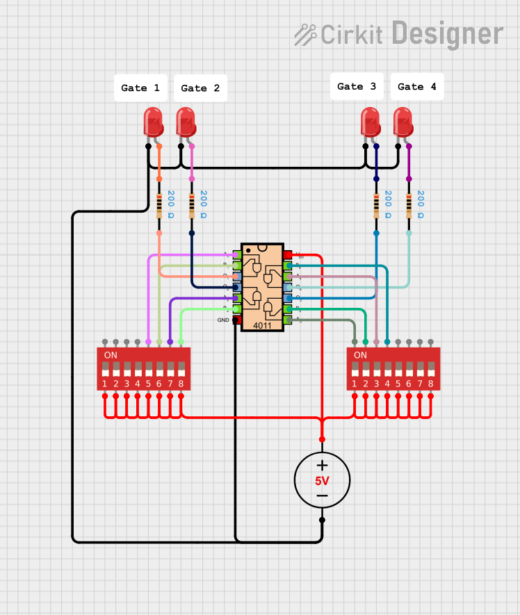
Circuit Documentation
Summary
This circuit is designed to utilize a combination of DIP switches, LED indicators, resistors, and a NAND gate IC to create a simple control mechanism. The DIP switches allow for user input, which is processed by the NAND gate, and the output is indicated through multiple LEDs. The circuit is powered by a 5V DC power supply.
Component List
5V DC Power Supply
- Description: Provides the necessary power for the circuit.
- Pins:
- Positive
- Negative
LED Two Pin (Red)
- Description: Indicates the status of the circuit through visual feedback.
- Pins:
- Cathode
- Anode
DIP Switch (8 Position)
- Description: Allows user input to control the circuit's behavior.
- Pins:
- 1a, 1b
- 2a, 2b
- 3a, 3b
- 4a, 4b
- 5a, 5b
- 6a, 6b
- 7a, 7b
- 8a, 8b
Resistor
- Description: Limits current flow in the circuit to protect components.
- Pins:
- pin1
- pin2
- Resistance: 200 Ohms
CD4011 Quad Input NAND Gate IC
- Description: Performs logical NAND operations based on the inputs from the DIP switches.
- Pins:
- VDD (14)
- GND (7)
- A1 (1), B1 (2)
- A2 (5), B2 (6)
- A3 (8), B3 (9)
- A4 (12), B4 (13)
- Q1 (3), Q2 (4), Q3 (10), Q4 (11)
Wiring Details
5V DC Power Supply
Positive connects to:
- DIP Switch (1a)
Negative connects to:
- LED (Cathode)
- LED (Cathode)
- LED (Cathode)
- LED (Cathode)
- CD4011 (GND)
LED Two Pin (Red) - Instance 1
Cathode connects to:
- CD4011 (GND)
Anode connects to:
- Resistor (pin1)
LED Two Pin (Red) - Instance 2
Cathode connects to:
- CD4011 (GND)
Anode connects to:
- Resistor (pin1)
LED Two Pin (Red) - Instance 3
Cathode connects to:
- CD4011 (GND)
Anode connects to:
- Resistor (pin1)
Resistor - Instance 1
pin1 connects to:
- LED (Anode)
pin2 connects to:
- CD4011 (Q1)
Resistor - Instance 2
pin1 connects to:
- LED (Anode)
pin2 connects to:
- CD4011 (Q2)
Resistor - Instance 3
pin1 connects to:
- LED (Anode)
pin2 connects to:
- CD4011 (Q3)
Resistor - Instance 4
pin1 connects to:
- LED (Anode)
pin2 connects to:
- CD4011 (Q4)
CD4011 Quad Input NAND Gate IC
VDD (14) connects to:
- DIP Switch (3a)
- DIP Switch (4a)
- DIP Switch (5a)
- DIP Switch (6a)
- DIP Switch (7a)
- DIP Switch (8a)
A1 (1) connects to:
- DIP Switch (5b)
B1 (2) connects to:
- DIP Switch (6b)
A2 (5) connects to:
- DIP Switch (7b)
B2 (6) connects to:
- DIP Switch (8b)
A3 (8) connects to:
- DIP Switch (1b)
B3 (9) connects to:
- DIP Switch (2b)
A4 (12) connects to:
- DIP Switch (3b)
B4 (13) connects to:
- DIP Switch (4b)
Documented Code
There is currently no code associated with the microcontrollers in this circuit.
This documentation provides a comprehensive overview of the circuit, detailing each component and its connections.