
Teensy 4.1 Based Biometric Data Acquisition System with AD8232 Heart Rate Monitor and LIS3DH Accelerometer
View and Edit Project In Cirkit Designer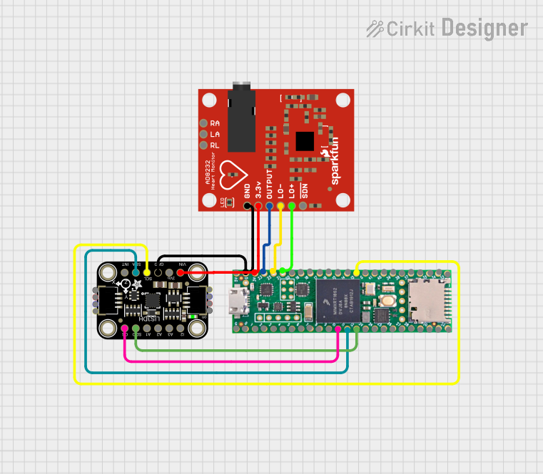
Circuit Documentation
Summary
The circuit in question is designed to interface a Teensy 4.1 microcontroller with an Adafruit LIS3DH Triple-Axis Accelerometer and an AD8232 Heart Rate Monitor. The Teensy 4.1 serves as the central processing unit, collecting data from the accelerometer and the heart rate monitor. The accelerometer is connected via SPI and I2C communication protocols, while the heart rate monitor is interfaced through analog and digital pins for signal output and status indication.
Component List
Adafruit LIS3DH Triple-Axis Accelerometer
- Description: A low-power triple-axis accelerometer with digital output for three acceleration axes.
- Pins: CS, SDO, ADC1, ADC2, ADC3, INT2, VCC, 3.3V, GND, SCL, SDA, INT1
Teensy 4.1
- Description: A high-performance microcontroller board based on the ARM Cortex-M7 processor, capable of running at a clock speed of up to 600 MHz.
- Pins: Ground, 0-33, 3v, 5V/Input, 3V, 23-41
AD8232 Heart Rate Monitor
- Description: A single-lead heart rate monitor front end, used for measuring the electrical activity of the heart.
- Pins: GND, 3.3v, OUTPUT, LO-, LO+, SDN, RA, LA, RL
Wiring Details
Adafruit LIS3DH Triple-Axis Accelerometer
- CS connected to Teensy 4.1 pin 10
- SDA connected to Teensy 4.1 pin 11
- SDO connected to Teensy 4.1 pin 12
- GND connected to Teensy 4.1 Ground
- VCC connected to Teensy 4.1 3V
- SCL connected to Teensy 4.1 pin 13
Teensy 4.1
- Pin 10 connected to Adafruit LIS3DH CS
- Pin 11 connected to Adafruit LIS3DH SDA
- Pin 12 connected to Adafruit LIS3DH SDO
- Ground connected to Adafruit LIS3DH GND and AD8232 GND
- 3V connected to Adafruit LIS3DH VCC and AD8232 3.3v
- Pin 23 connected to AD8232 OUTPUT
- Pin 22 connected to AD8232 LO-
- Pin 21 connected to AD8232 LO+
- Pin 13 connected to Adafruit LIS3DH SCL
AD8232 Heart Rate Monitor
- GND connected to Teensy 4.1 Ground
- 3.3v connected to Teensy 4.1 3V
- OUTPUT connected to Teensy 4.1 pin 23
- LO- connected to Teensy 4.1 pin 22
- LO+ connected to Teensy 4.1 pin 21
Documented Code
No code has been provided for the microcontrollers in the circuit. The documentation of the code would typically include setup routines, main loop, interrupt service routines, and any functions for data processing or communication. Since no code is available, this section cannot be completed at this time.