ESP32-Based RFID Access Control System with Motion Detection and Servo Lock Mechanism

Circuit Documentation
Summary
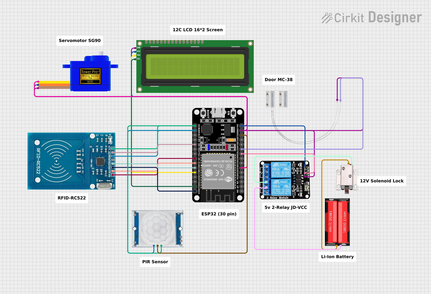
This circuit is designed to interface an ESP32 microcontroller with a variety of peripherals including an RFID-RC522 module, an I2C LCD 16x2 screen, a Servomotor SG90, a Door MC-38 magnetic contact switch, a 5V 2-Relay module, a 12V solenoid lock, an 18650 Li-Ion battery, and an HC-SR501 PIR motion sensor. The ESP32 serves as the central processing unit, controlling the peripherals based on inputs from the RFID reader, the magnetic switch, and the motion sensor. The LCD screen displays system status, the relay module controls power to the solenoid lock, and the servomotor is likely used for some form of actuation. The system appears to be a security or access control system, utilizing RFID for identification, the solenoid lock for physical security, and the PIR sensor for motion detection.
Component List
ESP32 (30 pin)
- Microcontroller with WiFi and Bluetooth capabilities.
- 30 GPIO pins including digital, analog, and power pins.
RFID-RC522
- RFID reader module for reading RFID tags.
- Communicates with the microcontroller via SPI.
I2C LCD 16x2 Screen
- Alphanumeric liquid crystal display with 16 characters by 2 lines.
- Uses I2C communication protocol.
Servomotor SG90
- Small and lightweight servo motor for precise control.
- Typically used for small-scale robotics and control applications.
Door MC-38
- Magnetic contact switch used to detect the opening and closing of doors or windows.
5v 2-Relay JD-VCC
- Relay module with two channels.
- Allows for controlling high power devices with low power signals from the microcontroller.
12V Solenoid Lock
- Electrically controlled lock that can be used for securing doors or drawers.
18650 Li-Ion Battery
- Rechargeable lithium-ion battery commonly used in portable electronics.
HC-SR501 PIR Motion Sensor
- Passive infrared sensor used to detect motion based on changes in infrared radiation.
Wiring Details
ESP32 (30 pin)
D32connected to Servomotor SG90 signal pin.D26connected to Relay module IN1.D27connected to Door MC-38 signal pin.D13connected to PIR motion sensor output.GNDconnected to common ground.Vinconnected to 5V power from the relay module.D23,D22,D21,D19,D18,D5,D4connected to RFID-RC522 SPI and I2C pins.3V3connected to 3.3V power for the RFID-RC522 and PIR motion sensor.
RFID-RC522
MOSI,MISO,SCK,SDA,RSTconnected to corresponding ESP32 pins.GNDconnected to common ground.VCC (3.3V)connected to 3.3V power from ESP32.
I2C LCD 16x2 Screen
SCL,SDAconnected to corresponding ESP32 pins.GNDconnected to common ground.VCC (5V)connected to 5V power from the relay module.
Servomotor SG90
SIGconnected to ESP32 D32.GNDconnected to common ground.VCCconnected to 5V power from the relay module.
Door MC-38
Sconnected to ESP32 D27.GNDconnected to common ground.
5v 2-Relay JD-VCC
IN1connected to ESP32 D26.GNDconnected to common ground.VCCconnected to 5V power from the I2C LCD screen.NOconnected to 12V solenoid lock VCC.COMconnected to 18650 Li-Ion battery positive.
12V Solenoid Lock
VCCconnected to Relay module NO.GNDconnected to 18650 Li-Ion battery negative.
18650 Li-Ion Battery
Positiveconnected to Relay module COM.Negativeconnected to 12V solenoid lock GND.
HC-SR501 PIR Motion Sensor
Outputconnected to ESP32 D13.Groundconnected to common ground.Power Supplyconnected to 3.3V power from ESP32.
Documented Code
No code has been provided for the microcontroller. The expected code would handle the initialization and configuration of the peripherals, read inputs from the RFID reader, magnetic switch, and motion sensor, control the LCD display, and manage the state of the relay and servomotor based on the system's logic.