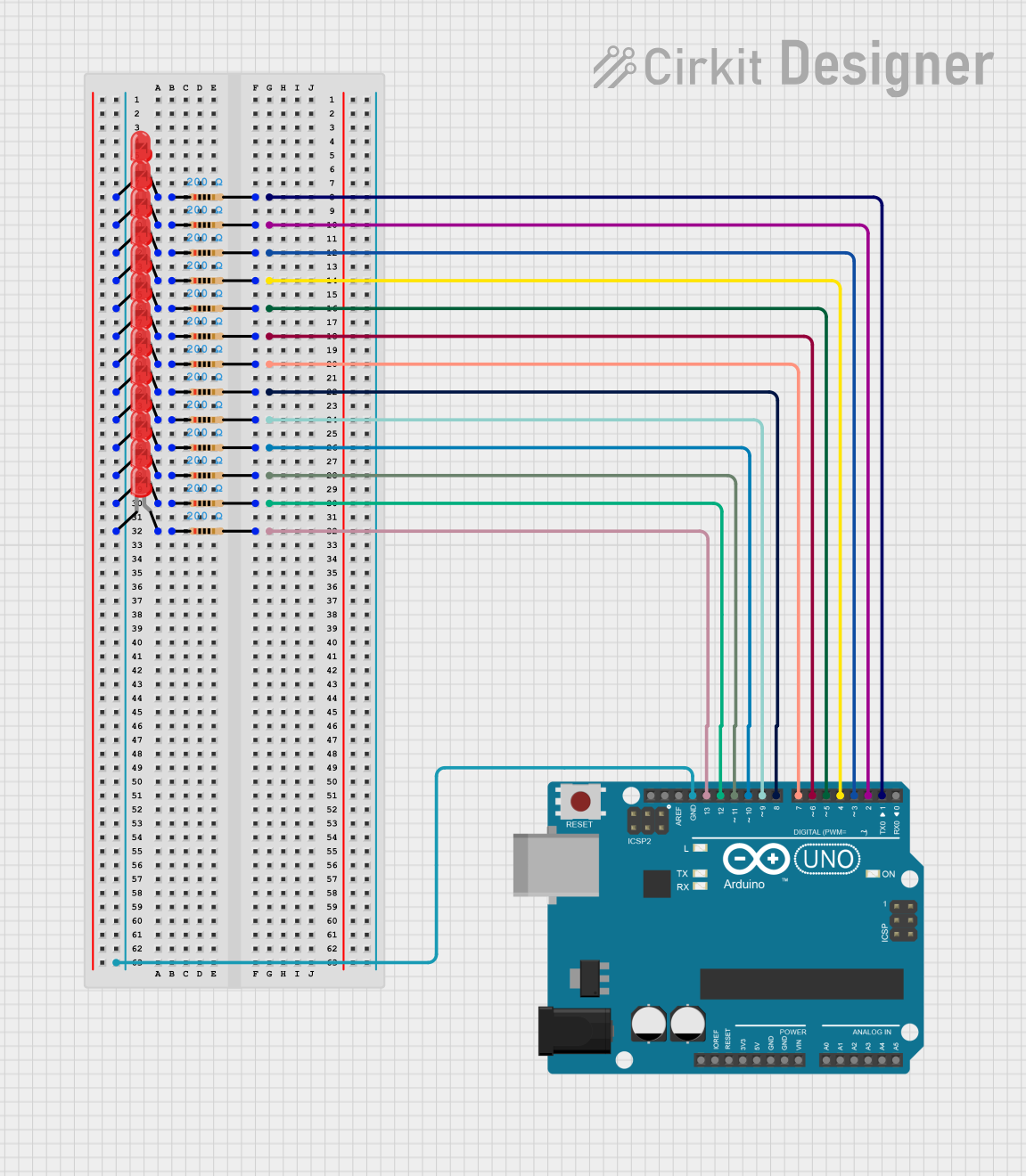
Arduino UNO Controlled LED Array

Circuit Documentation
Summary
The circuit in question appears to be a simple LED array controlled by an Arduino UNO microcontroller. Each LED is connected in series with a resistor to form a current-limiting circuit, and the other end of each LED-resistor pair is connected to a digital output pin on the Arduino UNO. The cathodes of all LEDs are tied together and connected to the ground (GND) pin of the Arduino UNO. This setup suggests that the LEDs can be individually controlled by the Arduino to turn on or off by setting the corresponding digital pins to HIGH or LOW.
Component List
Microcontroller
- Arduino UNO: A microcontroller board based on the ATmega328P. It has 14 digital input/output pins, 6 analog inputs, a USB connection, a power jack, an ICSP header, and a reset button.
LEDs
- LED: Two Pin (red): A standard red LED with an anode and cathode pin for emitting red light when a forward current passes through it.
Resistors
- Resistor: A passive two-terminal electrical component that implements electrical resistance as a circuit element. In this circuit, resistors are used to limit the current flowing through the LEDs. Each resistor has a value of 200 Ohms.
Wiring Details
Arduino UNO
- Digital pins D1 to D13 are each connected to a resistor.
- GND pin is connected to the cathodes of all LEDs.
LEDs
- Each LED has its anode connected to a resistor and its cathode connected to the GND pin of the Arduino UNO.
Resistors
- Each resistor is connected between an Arduino UNO digital pin (D1 to D13) and the anode of a corresponding LED.
Documented Code
Arduino UNO Code (sketch.ino)
void setup() {
  // put your setup code here, to run once:

}

void loop() {
  // put your main code here, to run repeatedly:

}
The provided code is a template with empty setup() and loop() functions. The setup() function is intended for code that runs once at the start, such as pin initialization. The loop() function contains code that runs repeatedly, which would typically control the LEDs in this circuit.
Additional Notes
- The code for the Arduino UNO is currently a placeholder and needs to be populated with the logic to control the LEDs.
- The
documentation.txtfile is empty and does not contain any additional information about the code or circuit.
This documentation provides an overview of the circuit's components and wiring, along with the initial code setup for the Arduino UNO. Further development of the code is required to achieve the desired functionality of the LED array.