
Arduino Nano-Based Self-Balancing Robot with MPU6050 and Stepper Motor
View and Edit Project In Cirkit Designer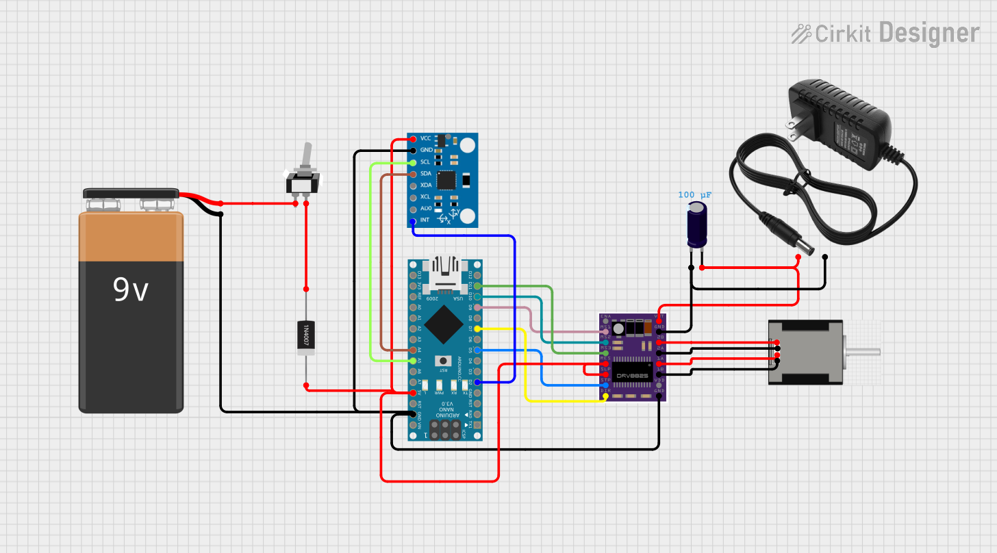
Circuit Documentation
Summary
This circuit is designed to control a NEMA 17 stepper motor using an Arduino Nano and a DRV8825 stepper motor driver. The system also includes an MPU6050 sensor for motion detection and a toggle switch for power control. The circuit is powered by a 9V battery and a 12V power supply. The Arduino Nano runs a PID control algorithm to maintain balance based on the MPU6050 sensor readings.
Component List
Arduino Nano
- Description: Microcontroller board based on the ATmega328P.
- Pins: D1/TX, D0/RX, RESET, GND, D2, D3, D4, D5, D6, D7, D8, D9, D10, D11/MOSI, D12/MISO, VIN, 5V, A7, A6, A5, A4, A3, A2, A1, A0, AREF, 3V3, D13/SCK
9V Battery
- Description: Power source for the circuit.
- Pins: -, +
DRV8825
- Description: Stepper motor driver.
- Pins: ENABLE, MS1, MS2, MS3, RESET, SLEEP, STEP, DIR, GND, FAULT, 1B, 1A, 2A, 2B, VMOT
NEMA 17 HS4401
- Description: Stepper motor.
- Pins: RED (B2), BLACK (B1), BLUE (A2), GREEN (A1)
12V Power Supply
- Description: Power source for the DRV8825 and stepper motor.
- Pins: +, -
Toggle Switch SPST
- Description: Single-pole single-throw switch for power control.
- Pins: L1, COM
MPU6050
- Description: 6-axis motion tracking device.
- Pins: vcc, gnd, scl, sda, xda, xcl, AD0, int, 3.3v
1N4007 Rectifier Diode
- Description: Diode for rectification.
- Pins: Cathode, Anode
Electrolytic Capacitor
- Description: Capacitor for filtering.
- Pins: -, +
- Properties: Capacitance: 0.0001 Farads
Wiring Details
Arduino Nano
- D2: Connected to MPU6050 (int)
- D5: Connected to DRV8825 (STEP)
- D7: Connected to DRV8825 (DIR)
- D9: Connected to DRV8825 (MS1)
- D10: Connected to DRV8825 (MS2)
- D11/MOSI: Connected to DRV8825 (MS3)
- GND: Connected to 9V Battery (-), MPU6050 (gnd), DRV8825 (GND)
- 5V: Connected to MPU6050 (vcc), DRV8825 (RESET), DRV8825 (SLEEP), 1N4007 Rectifier Diode (Cathode)
- A5: Connected to MPU6050 (scl)
- A4: Connected to MPU6050 (sda)
9V Battery
- -: Connected to MPU6050 (gnd), DRV8825 (GND), Arduino Nano (GND)
- +: Connected to Toggle Switch SPST (L1)
DRV8825
- STEP: Connected to Arduino Nano (D5)
- DIR: Connected to Arduino Nano (D7)
- MS1: Connected to Arduino Nano (D9)
- MS2: Connected to Arduino Nano (D10)
- MS3: Connected to Arduino Nano (D11/MOSI)
- GND: Connected to 9V Battery (-), MPU6050 (gnd), Arduino Nano (GND), Electrolytic Capacitor (-), 12V Power Supply (-)
- RESET: Connected to Arduino Nano (5V)
- SLEEP: Connected to Arduino Nano (5V)
- 1B: Connected to NEMA 17 HS4401 (GREEN (A1))
- 1A: Connected to NEMA 17 HS4401 (BLUE (A2))
- 2A: Connected to NEMA 17 HS4401 (BLACK (B1))
- 2B: Connected to NEMA 17 HS4401 (RED (B2))
- VMOT: Connected to Electrolytic Capacitor (+), 12V Power Supply (+)
NEMA 17 HS4401
- GREEN (A1): Connected to DRV8825 (1B)
- BLUE (A2): Connected to DRV8825 (1A)
- BLACK (B1): Connected to DRV8825 (2A)
- RED (B2): Connected to DRV8825 (2B)
12V Power Supply
- -: Connected to Electrolytic Capacitor (-), DRV8825 (GND)
- +: Connected to Electrolytic Capacitor (+), DRV8825 (VMOT)
Toggle Switch SPST
- L1: Connected to 9V Battery (+)
- COM: Connected to 1N4007 Rectifier Diode (Anode)
MPU6050
- int: Connected to Arduino Nano (D2)
- gnd: Connected to 9V Battery (-), DRV8825 (GND), Arduino Nano (GND)
- vcc: Connected to Arduino Nano (5V), DRV8825 (RESET), DRV8825 (SLEEP)
- scl: Connected to Arduino Nano (A5)
- sda: Connected to Arduino Nano (A4)
1N4007 Rectifier Diode
- Cathode: Connected to Arduino Nano (5V)
- Anode: Connected to Toggle Switch SPST (COM)
Electrolytic Capacitor
- -: Connected to DRV8825 (GND), 12V Power Supply (-)
- +: Connected to DRV8825 (VMOT), 12V Power Supply (+)
Documented Code
#include "I2Cdev.h"
#include <PID_v1.h>
#include "MPU6050_6Axis_MotionApps20.h"
#include <AccelStepper.h>

MPU6050 mpu;

// Stepper motor setup
#define STEP_PIN 5  // Step pin for the stepper motor
#define DIR_PIN 7   // Direction pin for the stepper motor

AccelStepper stepper(AccelStepper::DRIVER, STEP_PIN, DIR_PIN);

// MPU6050 variables
bool dmpReady = false;
uint8_t mpuIntStatus, devStatus;
uint16_t packetSize, fifoCount;
uint8_t fifoBuffer[64];
Quaternion q;
VectorFloat gravity;
float ypr[3];

double setpoint = 186;
double Kp = 150, Kd = 40, Ki = 3000;
double input, output;

//log
//Kp = 250, Kd = 55, Ki = 2500; jittery unstable
//Kp = 210, Kd = 35, Ki = 2000; mid response medy ok2 na 15s+?
// double Kp = 210, Kd = 30, Ki = 3200; good reesponse 30s+ pero unsstable pa gamay
//Kp = 210, Kd = 30, Ki = 3500; stable
//Kp = 210, Kd = 30, Ki = 3500;
//Kp = 150, Kd = 25, Ki = 1800;

PID pid(&input, &output, &setpoint, Kp, Ki, Kd, DIRECT);
volatile bool mpuInterrupt = false;

void dmpDataReady() {
  mpuInterrupt = true;
}

void setup() {
  Serial.begin(115200);

  // Initialize MPU6050
  //Serial.println(F("Initializing I2C devices..."));
  mpu.initialize();
  //Serial.println(mpu.testConnection() ? F("MPU6050 connection successful") : F("MPU6050 connection failed"));

  devStatus = mpu.dmpInitialize();
  if (devStatus == 0) {
    mpu.setXGyroOffset(220);
    mpu.setYGyroOffset(76);
    mpu.setZGyroOffset(-85);
    mpu.setZAccelOffset(1688);

    mpu.setDMPEnabled(true);
    attachInterrupt(digitalPinToInterrupt(2), dmpDataReady, RISING);
    mpuIntStatus = mpu.getIntStatus();
    dmpReady = true;
    packetSize = mpu.dmpGetFIFOPacketSize();

    pid.SetMode(AUTOMATIC);
    pid.SetSampleTime(10);
    pid.SetOutputLimits