Arduino UNO R4 WiFi Controlled Light Sensor with Dual LED Indicator
Circuit Documentation
Summary
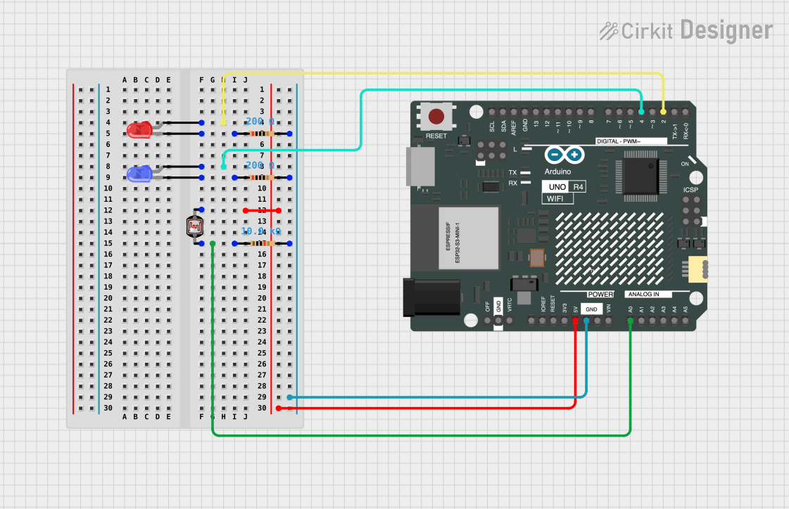
This circuit is designed to control two LEDs (one red and one blue) based on the light intensity detected by a photocell (Light Dependent Resistor, LDR). The Arduino UNO R4 WiFi microcontroller reads the analog value from the LDR and determines whether the environment is dark or light. If the LDR is covered (indicating darkness), the blue LED blinks. If the LDR is uncovered (indicating light), the red LED blinks. The circuit includes resistors for current limiting and voltage division purposes.
Component List
Arduino UNO R4 WiFi
- Microcontroller board with WiFi capability.
- It has a variety of digital and analog pins for interfacing with various components.
Photocell (LDR)
- A light-sensitive device used to detect the level of ambient light.
- Changes resistance based on the amount of light it is exposed to.
Resistors
- Three resistors are used in the circuit.
- Two resistors with a value of 200 Ohms are used for current limiting for the LEDs.
- One resistor with a value of 10,000 Ohms is used in conjunction with the LDR to form a voltage divider.
LED: Two Pin (red)
- A red light-emitting diode used as an indicator.
- Lights up when the LDR detects a high level of ambient light.
LED: Two Pin (blue)
- A blue light-emitting diode used as an indicator.
- Lights up when the LDR detects a low level of ambient light (or is covered).
Wiring Details
Arduino UNO R4 WiFi
- Digital Pin D2 is connected to the anode of the red LED.
- Digital Pin D4 is connected to the anode of the blue LED.
- Analog Pin A0 is connected to one side of the LDR.
- Pin 5V provides power to the other side of the LDR.
- GND is connected to the common ground rail with all resistors.
Photocell (LDR)
- One side is connected to the 5V supply from the Arduino.
- The other side is connected to the Arduino's Analog Pin A0 and to a 10,000 Ohm resistor going to ground.
Resistors
- A 200 Ohm resistor is connected in series with the cathode of each LED and to the ground rail.
- A 10,000 Ohm resistor is connected from the LDR to the ground rail.
LED: Two Pin (red)
- The anode is connected to Digital Pin D2 of the Arduino.
- The cathode is connected to a 200 Ohm resistor going to the ground rail.
LED: Two Pin (blue)
- The anode is connected to Digital Pin D4 of the Arduino.
- The cathode is connected to a 200 Ohm resistor going to the ground rail.
Documented Code
/*
 * This Arduino sketch controls two LEDs based on the input from a photocell (LDR).
 * When the photocell is uncovered, the red LED blinks. When the photocell is
 * covered, the blue LED blinks.
 */

const int redLEDPin = 2; // Pin connected to the anode of the red LED
const int blueLEDPin = 4; // Pin connected to the anode of the blue LED
const int ldrPin = A0; // Pin connected to the LDR
const int threshold = 500; // Threshold value to determine covered/uncovered state

void setup() {
  pinMode(redLEDPin, OUTPUT); // Set red LED pin as output
  pinMode(blueLEDPin, OUTPUT); // Set blue LED pin as output
  pinMode(ldrPin, INPUT); // Set LDR pin as input
}

void loop() {
  int ldrValue = analogRead(ldrPin); // Read the value from the LDR
  if (ldrValue < threshold) {
    // If LDR is covered, blink the blue LED
    digitalWrite(blueLEDPin, HIGH);
    delay(500);
    digitalWrite(blueLEDPin, LOW);
    delay(500);
  } else {
    // If LDR is uncovered, blink the red LED
    digitalWrite(redLEDPin, HIGH);
    delay(500);
    digitalWrite(redLEDPin, LOW);
    delay(500);
  }
}
The code is written for the Arduino platform and is saved with the .ino file extension. It initializes the pins connected to the LEDs and the LDR, then continuously reads the LDR value in the loop function. Depending on the light intensity, it blinks the appropriate LED.