Cirkit Designer
Your all-in-one circuit design IDE
Home /
Project Documentation
Arduino-Controlled RGB LED Strip with Hall Effect Sensor and MOSFET Dimming
Circuit Documentation
Summary
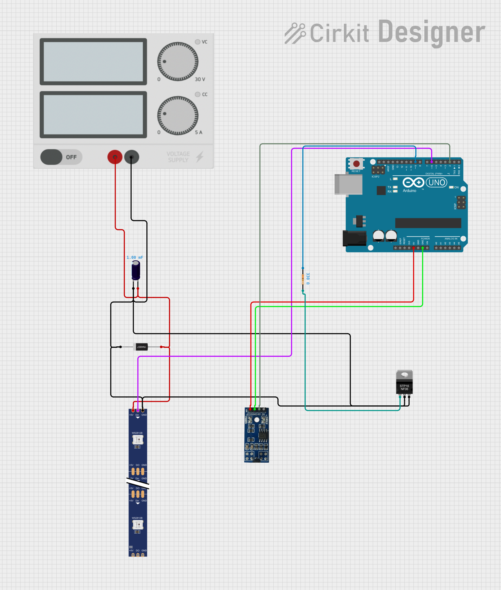
The circuit in question is designed to control an RGB LED strip using an Arduino UNO microcontroller. It includes a Hall effect sensor for detecting magnetic fields, a power MOSFET for controlling high-current loads, a rectifier diode for protecting against reverse polarity, and an electrolytic capacitor for voltage smoothing. The circuit is powered by an external power supply and includes a resistor for current limiting or pull-up purposes.
Component List
Electrolytic Capacitor
- Description: A capacitor used for filtering and smoothing out voltage fluctuations.
- Properties:
- Capacitance: 0.001 Farads
1N4007 Rectifier Diode
- Description: A diode that allows current to flow in only one direction, used for reverse polarity protection.
- Properties: None specified.
WS2812 RGB LED Strip
- Description: A strip of RGB LEDs that can be individually controlled using a digital signal.
- Properties: None specified.
Hall Sensor (Magnetic)
- Description: A sensor that detects magnetic fields and outputs a digital or analog signal.
- Properties: None specified.
STP16NF06 N-Channel Power MOSFET
- Description: A transistor used for switching and amplifying electronic signals.
- Properties: None specified.
Arduino UNO
- Description: A microcontroller board based on the ATmega328P, used for controlling the components in the circuit.
- Properties: None specified.
Power Supply
- Description: Provides the necessary power to the circuit.
- Properties: None specified.
Resistor
- Description: A passive two-terminal electrical component that implements electrical resistance as a circuit element.
- Properties:
- Resistance: 330 Ohms
Wiring Details
Electrolytic Capacitor
- Negative Pin: Connected to the ground net, which includes the GND pin of the power supply, the GND pin of the WS2812 RGB LED strip, the drain and source pins of the MOSFET, and the cathode of the rectifier diode.
- Positive Pin: Connected to the positive voltage net, which includes the + pin of the power supply, the 5V pin of the WS2812 RGB LED strip, and the anode of the rectifier diode.
1N4007 Rectifier Diode
- Cathode: Connected to the ground net.
- Anode: Connected to the positive voltage net.
WS2812 RGB LED Strip
- DIN: Connected to pin D6 of the Arduino UNO.
- 5V: Connected to the positive voltage net.
- GND: Connected to the ground net.
- DO: Not connected in the provided net list.
Hall Sensor (Magnetic)
- VCC (5V): Connected to the 5V pin of the Arduino UNO.
- GND: Connected to the GND pin of the Arduino UNO.
- D0 (Digital): Connected to pin D2 of the Arduino UNO.
- A0 (Analog): Not connected in the provided net list.
STP16NF06 N-Channel Power MOSFET
- Gate: Connected to pin D9 of the Arduino UNO through a 330 Ohm resistor.
- Drain: Connected to the ground net.
- Source: Connected to the ground net.
Arduino UNO
- D6: Connected to the DIN pin of the WS2812 RGB LED strip.
- D9: Connected to the gate of the MOSFET through a 330 Ohm resistor.
- D2: Connected to the D0 (Digital) pin of the Hall sensor.
- 5V: Connected to the VCC (5V) pin of the Hall sensor.
- GND: Connected to the GND pin of the Hall sensor.
Power Supply
- +: Connected to the positive voltage net.
- -: Connected to the ground net.
Resistor
- Pin1: Connected to pin D9 of the Arduino UNO.
- Pin2: Connected to the gate of the MOSFET.
Documented Code
Arduino UNO Code (sketch.ino)
#include <Adafruit_NeoPixel.h>

#define SENSOR_PIN 2      // Sensor input pin (Reed Switch or Hall Effect Sensor)
#define LED_PIN 6         // LED strip control pin
#define MOSFET_PIN 9      // MOSFET control pin
#define NUM_LEDS 60       // Number of LEDs in the strip

Adafruit_NeoPixel strip = Adafruit_NeoPixel(NUM_LEDS, LED_PIN, NEO_GRB + NEO_KHZ800);

volatile unsigned long lastDebounceTime = 0;
volatile unsigned int pulseCount = 0;
unsigned long previousMillis = 0;

void setup() {
  pinMode(SENSOR_PIN, INPUT_PULLUP);
  pinMode(MOSFET_PIN, OUTPUT);
  attachInterrupt(digitalPinToInterrupt(SENSOR_PIN), countPulse, FALLING);

  strip.begin();
  strip.show();  // Initialize all pixels to 'off'
}

void loop() {
  unsigned long currentMillis = millis();

  // Calculate speed based on pulse count
  if (currentMillis - previousMillis >= 1000) {
    previousMillis = currentMillis;

    int speed = pulseCount;
    pulseCount = 0;

    // Map speed to brightness (0-255)
    int brightness = map(speed, 0, 50, 0, 255);
    brightness = constrain(brightness, 0, 255);

    // Control the brightness of the LEDs
    strip.setBrightness(brightness);
    for(int i=0; i<strip.numPixels(); i++) {
      strip.setPixelColor(i, strip.Color(255, 0, 0));  // Set color to red (can be changed)
    }
    strip.show();

    // Control the MOSFET (if needed)
    analogWrite(MOSFET_PIN, brightness);
  }
}

void countPulse() {
  if ((millis() - lastDebounceTime) > 50) {  // Debounce
    pulseCount++;
    lastDebounceTime = millis();
  }
}
Note: The code provided for the microcontroller with instance ID b23d5d2a-02ba-4f89-99c2-8dda9a2b75b1 is empty and thus not included in the documentation.