
Arduino-Controlled UV LED Sterilization System with Dual UV Sensors
View and Edit Project In Cirkit Designer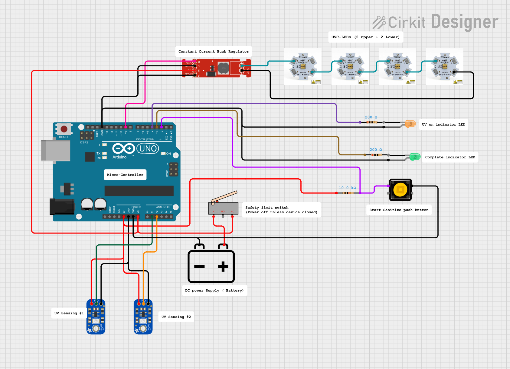
Circuit Documentation
Summary
This circuit is designed to control a set of UV LEDs using an Arduino UNO. The UV LEDs are powered through a constant current regulator and are monitored by UV light sensors. The process is initiated by a push button and continues until the UV sensors detect a desired UV level. During the operation, an indicator LED is lit, and upon completion, a green LED is turned on while the UV LEDs are turned off.
Component List
Adafruit GUVA-S12SD UV Light Sensor
- Pins: 5V, Out, GND
- Description: UV light sensor to measure UV intensity.
Arduino UNO
- Pins: UNUSED, IOREF, Reset, 3.3V, 5V, GND, Vin, A0, A1, A2, A3, A4, A5, SCL, SDA, AREF, D13, D12, D11, D10, D9, D8, D7, D6, D5, D4, D3, D2, D1, D0
- Description: Microcontroller to control the circuit.
Ultraviolet (UV-C) 275nm Seoul Viosys LED Module
- Pins: +, -
- Description: UV-C LED module for emitting UV light.
FemtoBuck LED Driver
- Pins: GND, VIN, CTRL_CH1, OUT+, OUT-
- Description: Constant current LED driver.
12v Battery
- Pins: -, +
- Description: Power source for the circuit.
LED: Two Pin (green)
- Pins: cathode, anode
- Description: Green indicator LED.
LED: Two Pin (orange)
- Pins: cathode, anode
- Description: Orange indicator LED.
Resistor (200 Ohms)
- Pins: pin1, pin2
- Description: Resistor with 200 Ohms resistance.
Resistor (10k Ohms)
- Pins: pin1, pin2
- Description: Resistor with 10k Ohms resistance.
Limit switch
- Pins: C, NO, NC
- Description: Switch to control the circuit.
Momentary Push Button Switch
- Pins: 1, 3, 2, 4
- Description: Button to start the process.
Wiring Details
Adafruit GUVA-S12SD UV Light Sensor
- 5V: Connected to 5V on Arduino UNO and pin1 of 10k Ohms resistor.
- Out: Connected to A1 on Arduino UNO.
- GND: Connected to GND on Arduino UNO.
Arduino UNO
- 5V: Connected to 5V pin of Adafruit GUVA-S12SD UV Light Sensor and pin1 of 10k Ohms resistor.
- A1: Connected to Out pin of Adafruit GUVA-S12SD UV Light Sensor.
- A2: Connected to Out pin of second Adafruit GUVA-S12SD UV Light Sensor.
- GND: Connected to GND pin of Adafruit GUVA-S12SD UV Light Sensor, GND pin of FemtoBuck LED Driver, and - pin of 12v Battery.
- Vin: Connected to VIN pin of FemtoBuck LED Driver and NC pin of Limit switch.
- D9: Connected to CTRL_CH1 pin of FemtoBuck LED Driver.
- D4: Connected to pin1 of 200 Ohms resistor.
- D3: Connected to pin1 of another 200 Ohms resistor.
- D2: Connected to pin3 of Momentary Push Button Switch.
Ultraviolet (UV-C) 275nm Seoul Viosys LED Module
- +: Connected to OUT+ pin of FemtoBuck LED Driver.
- -: Connected to OUT- pin of FemtoBuck LED Driver.
FemtoBuck LED Driver
- VIN: Connected to Vin on Arduino UNO and NC pin of Limit switch.
- CTRL_CH1: Connected to D9 on Arduino UNO.
- OUT+: Connected to + pin of Ultraviolet (UV-C) 275nm Seoul Viosys LED Module.
- OUT-: Connected to - pin of Ultraviolet (UV-C) 275nm Seoul Viosys LED Module.
- GND: Connected to GND on Arduino UNO and anode of orange and green LEDs.
12v Battery
- -: Connected to GND on Arduino UNO and pin4 of Momentary Push Button Switch.
- +: Connected to C pin of Limit switch.
LED: Two Pin (green)
- anode: Connected to GND on Arduino UNO.
- cathode: Not connected.
LED: Two Pin (orange)
- anode: Connected to GND on Arduino UNO.
- cathode: Not connected.
Resistor (200 Ohms)
- pin1: Connected to D4 on Arduino UNO.
- pin2: Not connected.
Resistor (10k Ohms)
- pin1: Connected to 5V on Arduino UNO and 5V pin of Adafruit GUVA-S12SD UV Light Sensor.
- pin2: Connected to pin3 of Momentary Push Button Switch.
Limit switch
- C: Connected to + pin of 12v Battery.
- NC: Connected to VIN pin of FemtoBuck LED Driver and Vin on Arduino UNO.
- NO: Not connected.
Momentary Push Button Switch
- 1: Not connected.
- 3: Connected to pin2 of 10k Ohms resistor and D2 on Arduino UNO.
- 2: Not connected.
- 4: Connected to - pin of 12v Battery.
Code Documentation
/*
 * This Arduino sketch controls a set of UV LEDs via a constant current regulator.
 * The UV LEDs remain powered until the UV sensor achieves a desired value.
 * While the UV LEDs are powered on, an indicator LED is lit.
 * When the process is complete, a green LED is powered, and the UV LEDs are turned off.
 * The process is started with the push of a button.
 */

const int uvSensorPin1 = A1; // UV sensor 1 output
const int uvSensorPin2 = A2; // UV sensor 2 output
const int uvLEDPin = 9;      // UV LED control pin
const int indicatorLEDPin = 3; // Indicator LED pin
const int greenLEDPin = 4;   // Green LED pin
const int buttonPin = 2;     // Button pin
const int desiredUVLevel = 500; // Desired UV sensor value

void setup() {
  pinMode(uvLEDPin, OUTPUT);
  pinMode(indicatorLEDPin, OUTPUT);
  pinMode(greenLEDPin, OUTPUT);
  pinMode(buttonPin, INPUT);
  digitalWrite(uvLEDPin, LOW);
  digitalWrite(indicatorLEDPin, LOW);
  digitalWrite(greenLEDPin, LOW);
}

void loop() {
  if (digitalRead(buttonPin) == HIGH) {
    digitalWrite(uvLEDPin, HIGH);
    digitalWrite(indicatorLEDPin, HIGH);
    while (analogRead(uvSensorPin1) < desiredUVLevel &&
           analogRead(uvSensorPin2) < desiredUVLevel) {
      // Wait until the desired UV level is reached
    }
    digitalWrite(uvLEDPin, LOW);
    digitalWrite(indicatorLEDPin, LOW);
    digitalWrite(greenLEDPin, HIGH);
  }
}
This code initializes the pins and sets the initial state of the LEDs to LOW. When the button is pressed, the UV LEDs and the indicator LED are turned on. The system then waits until the UV sensors detect the desired UV level. Once the desired level is reached, the UV LEDs and the indicator LED are turned off, and the green LED is turned on to indicate the completion of the process.