
ESP32-Based Wi-Fi Controlled Robotic Car with Ultrasonic Obstacle Avoidance
View and Edit Project In Cirkit Designer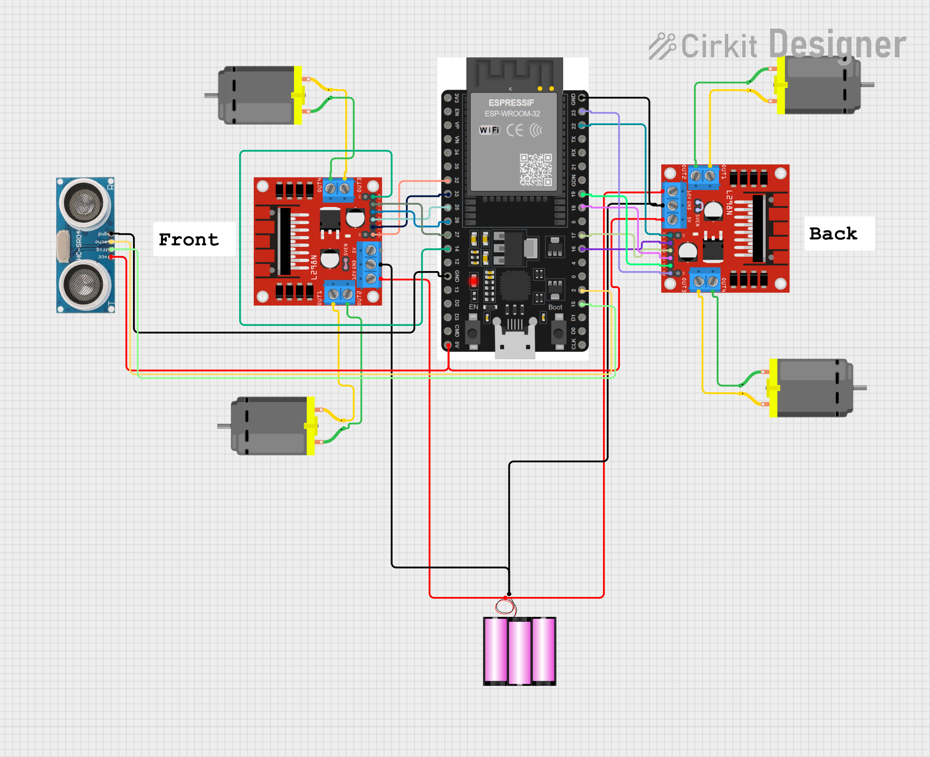
Circuit Documentation
Summary
This document provides a detailed overview of a circuit designed to control a robotic car using an ESP32 microcontroller. The car is equipped with four DC motors, an ultrasonic sensor for obstacle detection, and two L298N motor drivers to control the motors. The ESP32 microcontroller receives commands via ESP-NOW and controls the motors accordingly. The ultrasonic sensor is used to detect obstacles and stop the car if it gets too close to an object.
Component List
DC Motor
- Description: A simple DC motor used for driving the wheels of the robotic car.
- Pins: pin 1, pin 2
Battery 12V
- Description: A 12V battery used to power the motors and motor drivers.
- Pins: +, -
ESP32 38 PINS
- Description: A microcontroller used to control the motors and receive commands via ESP-NOW.
- Pins: GND, 23, 22/SCL, 1, 2, 21/SDA, 19, 18, 5, 17/TX2, 16/RX2, 4, 0, 15, D1, D0, CLK, 3V3, EN, VP, VN, 34, 35, 32, 33, 25, 26, 27, 14, 12, 13, D2, D3, 11, 5V/VIN
L298N DC Motor Driver
- Description: A motor driver used to control the speed and direction of the DC motors.
- Pins: OUT1, OUT2, 12V, GND, 5V, OUT3, OUT4, 5V-ENA-JMP-I, 5V-ENA-JMP-O, +5V-J1, +5V-J2, ENA, IN1, IN2, IN3, IN4, ENB
Ultrasonic Sensor
- Description: A sensor used to measure the distance to obstacles in front of the car.
- Pins: +VCC, Trigger, Echo, GND
Wiring Details
DC Motor
Motor 1:
- pin 1: Connected to OUT2 of L298N DC motor driver
- pin 2: Connected to OUT1 of L298N DC motor driver
Motor 2:
- pin 1: Connected to OUT2 of L298N DC motor driver
- pin 2: Connected to OUT1 of L298N DC motor driver
Motor 3:
- pin 1: Connected to OUT4 of L298N DC motor driver
- pin 2: Connected to OUT3 of L298N DC motor driver
Motor 4:
- pin 1: Connected to OUT4 of L298N DC motor driver
- pin 2: Connected to OUT3 of L298N DC motor driver
Battery 12V
- +: Connected to 12V of both L298N DC motor drivers
- -: Connected to GND of both L298N DC motor drivers and GND of ESP32
ESP32 38 PINS
- GND: Connected to GND of both L298N DC motor drivers and GND of Ultrasonic Sensor
- 23: Connected to ENB of L298N DC motor driver
- 22/SCL: Connected to ENA of L298N DC motor driver
- 19: Connected to IN4 of L298N DC motor driver
- 18: Connected to IN3 of L298N DC motor driver
- 17/TX2: Connected to IN2 of L298N DC motor driver
- 16/RX2: Connected to IN1 of L298N DC motor driver
- 2: Connected to Echo of Ultrasonic Sensor
- 15: Connected to Trigger of Ultrasonic Sensor
- 32: Connected to ENA of L298N DC motor driver
- 33: Connected to IN1 of L298N DC motor driver
- 25: Connected to IN2 of L298N DC motor driver
- 26: Connected to IN3 of L298N DC motor driver
- 27: Connected to IN4 of L298N DC motor driver
- 14: Connected to ENB of L298N DC motor driver
- 5V/VIN: Connected to 5V of L298N DC motor driver and +VCC of Ultrasonic Sensor
L298N DC Motor Driver
Driver 1:
- OUT1: Connected to pin 2 of Motor 1
- OUT2: Connected to pin 1 of Motor 1
- 12V: Connected to + of Battery 12V
- GND: Connected to GND of Battery 12V and GND of ESP32
- 5V: Connected to 5V/VIN of ESP32 and +VCC of Ultrasonic Sensor
- OUT3: Connected to pin 2 of Motor 3
- OUT4: Connected to pin 1 of Motor 3
- 5V-ENA-JMP-I: Connected to 5V-ENA-JMP-O of the same driver
- ENA: Connected to 32 of ESP32
- IN1: Connected to 33 of ESP32
- IN2: Connected to 25 of ESP32
- IN3: Connected to 26 of ESP32
- IN4: Connected to 27 of ESP32
- ENB: Connected to 14 of ESP32
Driver 2:
- OUT1: Connected to pin 2 of Motor 2
- OUT2: Connected to pin 1 of Motor 2
- 12V: Connected to + of Battery 12V
- GND: Connected to GND of Battery 12V and GND of ESP32
- 5V: Connected to 5V/VIN of ESP32 and +VCC of Ultrasonic Sensor
- OUT3: Connected to pin 2 of Motor 4
- OUT4: Connected to pin 1 of Motor 4
- 5V-ENA-JMP-I: Connected to 5V-ENA-JMP-O of the same driver
- ENA: Connected to 22/SCL of ESP32
- IN1: Connected to 16/RX2 of ESP32
- IN2: Connected to 17/TX2 of ESP32
- IN3: Connected to 18 of ESP32
- IN4: Connected to 19 of ESP32
- ENB: Connected to 23 of ESP32
Ultrasonic Sensor
- +VCC: Connected to 5V/VIN of ESP32
- Trigger: Connected to 15 of ESP32
- Echo: Connected to 2 of ESP32
- GND: Connected to GND of ESP32
Documented Code
#include <esp_now.h>
#include <WiFi.h>

#define FORWARD 1
#define BACKWARD 2
#define LEFT 3
#define RIGHT 4
#define FORWARD_LEFT 5
#define FORWARD_RIGHT 6
#define BACKWARD_LEFT 7
#define BACKWARD_RIGHT 8
#define TURN_LEFT 9
#define TURN_RIGHT 10
#define STOP 0

#define BACK_RIGHT_MOTOR 0
#define BACK_LEFT_MOTOR 1
#define FRONT_RIGHT_MOTOR 2
#define FRONT_LEFT_MOTOR 3
const int trigPin = 2;
const int echoPin = 3;
struct MOTOR_PINS
{
  int pinIN1;
  int pinIN2;
  int pinEn;
  int pwmSpeedChannel;
};

std::vector<MOTOR_PINS> motorPins =
{
  {16, 17, 22, 4},  //BACK_RIGHT_MOTOR
  {18, 19, 23, 5},  //BACK_LEFT_MOTOR
  {26, 27, 14, 6},  //FRONT_RIGHT_MOTOR
  {33, 25, 32, 7},  //FRONT_LEFT_MOTOR
};

#define MAX_MOTOR_SPEED 200

const int PWMFreq = 1000; /* 1 KHz */
const int PWMResolution = 8;

#define SIGNAL_TIMEOUT 1000  // This is signal timeout in milli seconds. We will reset the data if no signal
unsigned long lastRecvTime = 0;

struct PacketData
{
  byte xAxisValue;
  byte yAxisValue;
  byte zAxisValue;
};
PacketData receiverData;

// callback function that will be executed when data is received
void OnDataRecv(const uint8_t * mac, const uint8_t *incomingData, int len)
{
  if (len == 0)
  {
    return;
  }
  memcpy(&receiverData, incomingData, sizeof(receiverData));
  String inputData ;
  inputData = inputData + "values " + receiverData.xAxisValue + "  " + receiverData.yAxisValue + "  " + receiverData.zAxisValue;
  Serial.println(inputData);

  if ( receiverData.xAxisValue < 75 && receiverData.y