
Arduino UNO Based Ultrasonic Distance Sensor with Buzzer Alert
View and Edit Project In Cirkit Designer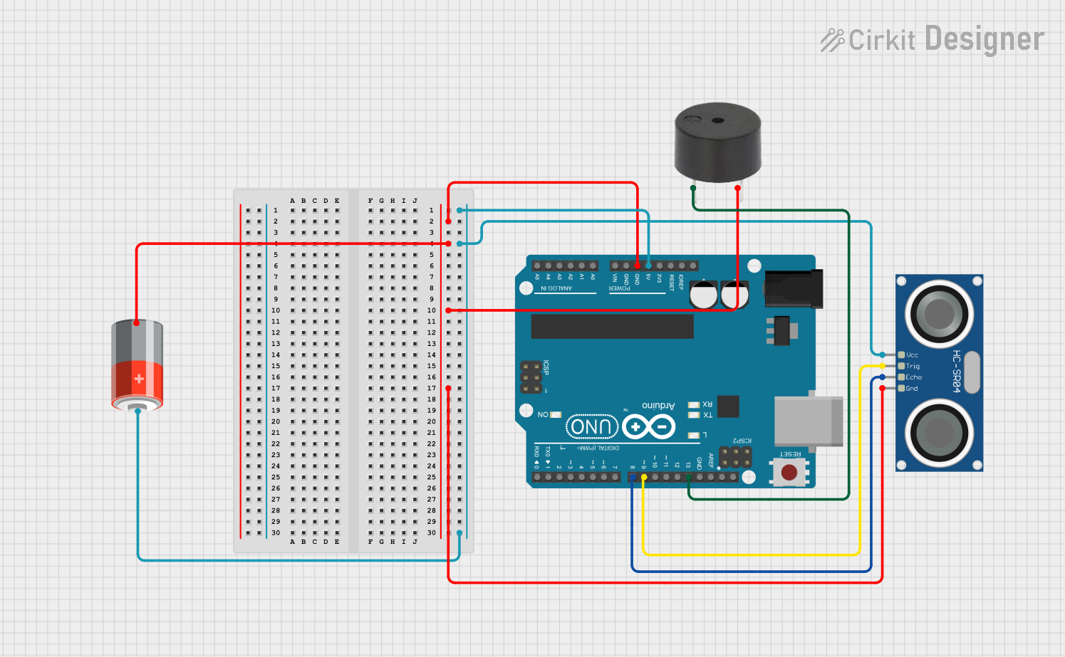
Circuit Documentation
Summary
This circuit is designed to measure distance using an HC-SR04 Ultrasonic Sensor and provide feedback through a buzzer if the measured distance is below a certain threshold. The Arduino UNO serves as the central processing unit, controlling the sensor and the buzzer. A 5V battery provides power to the system.
Component List
HC-SR04 Ultrasonic Sensor
- Pins: VCC, TRIG, ECHO, GND
- Description: This sensor measures distance by emitting ultrasonic waves and measuring the time taken for the echo to return.
Arduino UNO
- Pins: UNUSED, IOREF, Reset, 3.3V, 5V, GND, Vin, A0-A5, SCL, SDA, AREF, D0-D13
- Description: A microcontroller board based on the ATmega328P, used for controlling the logic of the circuit.
5V Battery
- Pins: +, -
- Description: Provides the power supply for the circuit.
Buzzer
- Pins: PIN, GND
- Description: An electromechanical component that produces sound when an electrical signal is applied.
Wiring Details
HC-SR04 Ultrasonic Sensor
- VCC: Connected to the 5V output from the Arduino UNO and the positive terminal of the 5V battery.
- TRIG: Connected to digital pin D9 on the Arduino UNO.
- ECHO: Connected to digital pin D8 on the Arduino UNO.
- GND: Common ground with the Arduino UNO, the negative terminal of the 5V battery, and the GND pin of the buzzer.
Arduino UNO
- 5V: Provides power to the HC-SR04 Ultrasonic Sensor.
- D9: Sends trigger signal to the HC-SR04 Ultrasonic Sensor.
- D8: Receives echo signal from the HC-SR04 Ultrasonic Sensor.
- D13: Controls the buzzer.
- GND: Common ground for the circuit.
5V Battery
- +: Provides power to the circuit, connected to the VCC of the HC-SR04 Ultrasonic Sensor and the 5V pin of the Arduino UNO.
- -: Common ground for the circuit.
Buzzer
- PIN: Connected to digital pin D13 on the Arduino UNO.
- GND: Common ground with the rest of the circuit.
Documented Code
Arduino UNO Code
#define trigPin 9           // Trig Pin Of HC-SR04
#define echoPin 8           // Echo Pin Of HC-SR04
#define BUZ 13              // BUZZER
long duration, distance;

void setup()
{
   pinMode(BUZ, OUTPUT);
   pinMode(trigPin, OUTPUT);       // Set Trig Pin As O/P To Transmit Waves
   pinMode(echoPin, INPUT);        // Set Echo Pin As I/P To Receive Reflected Waves
}

void loop()
{
  Serial.begin(9600);
  digitalWrite(trigPin, LOW);
  delayMicroseconds(2);
  digitalWrite(trigPin, HIGH);       // Transmit Waves For 10us
  delayMicroseconds(10);
  duration = pulseIn(echoPin, HIGH);        // Receive Reflected Waves
  distance = duration / 58.2;               // Calculate Distance
  Serial.println(distance);
  delay(10);
  if (distance < 15)                        // Condition For Distance Threshold
  {
    // Turn BUZZER ON & OFF 5 times:
    for (int i = 0; i < 5; i++)
    {
      digitalWrite(BUZ, HIGH);
      delay(50);
      digitalWrite(BUZ, LOW);
      delay(50);
    }
  }
}
Note: The code provided for the other microcontroller instances appears to be placeholders or empty and is therefore not included in this documentation.