Arduino UNO Controlled LCD Display with RTC and Servo Integration
Circuit Documentation
Summary
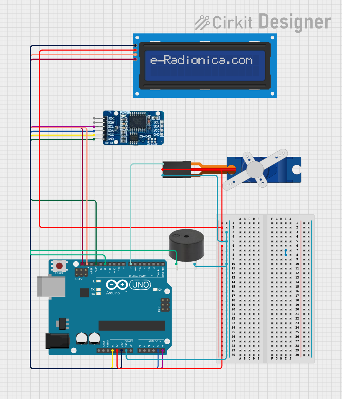
This circuit integrates an Arduino UNO microcontroller with several peripherals: an LCD screen (16x2 characters) with an I2C interface, a Tower Pro SG90 servo motor, a Real-Time Clock (RTC) module DS3231, and a buzzer. The Arduino UNO serves as the central processing unit, controlling the servo, displaying information on the LCD, and keeping track of time with the RTC. The buzzer is used for audible alerts or feedback. The circuit is designed to operate on a 5V supply from the Arduino UNO, with the exception of the RTC, which operates on 3.3V.
Component List
Arduino UNO
- Microcontroller board based on the ATmega328P
- Provides digital and analog I/O pins
- Features both 5V and 3.3V power outputs for peripherals
LCD screen 16x2 I2C
- Alphanumeric liquid crystal display
- Capable of displaying 16 characters per line across 2 lines
- Utilizes I2C for communication, reducing pin usage on the Arduino
Tower Pro SG90 servo
- Small and lightweight servo motor
- Operates on +5V and can be controlled via PWM signal
RTC DS3231
- Highly accurate real-time clock module
- Maintains time with a battery backup
- Communicates with the Arduino via I2C
Buzzer
- Simple piezoelectric buzzer
- Generates sound when powered
Wiring Details
Arduino UNO
5Vpin connected to the VCC of the LCD screen and the +5V of the servo3.3Vpin connected to the VCC of the RTC DS3231GNDpin connected to the GND of the servo, buzzer, LCD screen, and RTCA4 (SDA)pin connected to the SDA of the RTC DS3231 and LCD screenA5 (SCL)pin connected to the SCL of the RTC DS3231 and LCD screenD7pin connected to the Signal pin of the servoD12pin connected to the PIN of the buzzer
LCD screen 16x2 I2C
SCLandSDApins connected to the corresponding SCL and SDA on the Arduino UNOVCCconnected to the 5V output from the Arduino UNOGNDconnected to the ground on the Arduino UNO
Tower Pro SG90 servo
Signalpin connected to the D7 on the Arduino UNO+5Vpin connected to the 5V output from the Arduino UNOGNDpin connected to the ground on the Arduino UNO
RTC DS3231
SCLandSDApins connected to the corresponding SCL and SDA on the Arduino UNOVCCconnected to the 3.3V output from the Arduino UNOGNDconnected to the ground on the Arduino UNO
Buzzer
PINconnected to the D12 on the Arduino UNOGNDconnected to the ground on the Arduino UNO
Documented Code
Arduino UNO Code (sketch.ino)
void setup() {
  // put your setup code here, to run once:

}

void loop() {
  // put your main code here, to run repeatedly:

}
This is the basic structure of an Arduino sketch, with setup() function to initialize settings, and a loop() function that runs continuously. Additional code would be required to control the peripherals like the LCD, servo, RTC, and buzzer.