Cirkit Designer
Your all-in-one circuit design IDE
Home /
Project Documentation
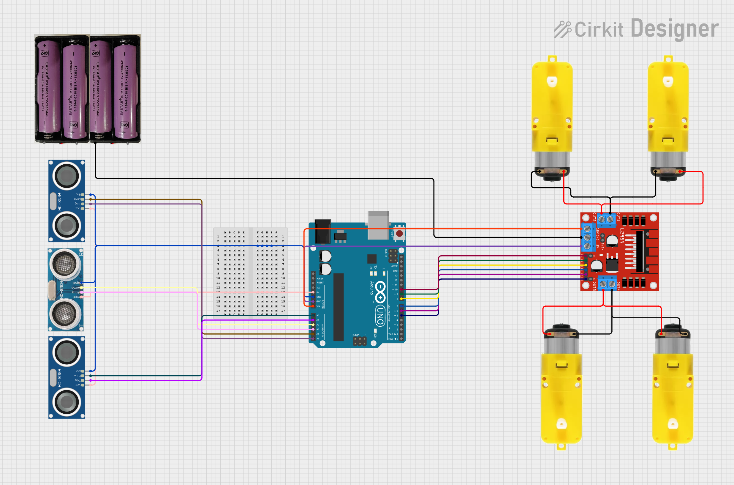
Arduino UNO and L298N Motor Driver-Based Obstacle Avoiding and Line Following Robot with Ultrasonic Sensors
Circuit Documentation
Summary
This document provides a detailed overview of a circuit designed to control multiple motors and ultrasonic sensors using an Arduino UNO and an L298N DC motor driver. The circuit includes various components such as motors with reducers, ultrasonic sensors, and a power supply. The Arduino UNO is programmed to control the motors and sensors based on input from an IR remote and Bluetooth communication.
Component List
L298N DC Motor Driver
- Description: Dual H-Bridge motor driver for controlling two DC motors.
- Pins: OUT1, OUT2, 12V, GND, 5V, OUT3, OUT4, 5V-ENA-JMP-I, 5V-ENA-JMP-O, +5V-J1, +5V-J2, ENA, IN1, IN2, IN3, IN4, ENB
Arduino UNO
- Description: Microcontroller board based on the ATmega328P.
- Pins: UNUSED, IOREF, Reset, 3.3V, 5V, GND, Vin, A0, A1, A2, A3, A4, A5, SCL, SDA, AREF, D13, D12, D11, D10, D9, D8, D7, D6, D5, D4, D3, D2, D1, D0
Motor with Reducer
- Description: DC motor with a gear reducer.
- Pins: 3 - 6 VCC, GND
7.4V Battery
- Description: Power supply for the circuit.
- Pins: +, -
Ultrasonic Sensor
- Description: Sensor for measuring distance using ultrasonic waves.
- Pins: +VCC, Trigger, Echo, GND
HC-SR04 Ultrasonic Sensor
- Description: Ultrasonic distance sensor.
- Pins: VCC, TRIG, ECHO, GND
Wiring Details
L298N DC Motor Driver
- GND connected to 7.4V Battery (-)
- OUT1 connected to Motor with Reducer (GND)
- OUT2 connected to Motor with Reducer (3 - 6 VCC)
- 12V connected to Arduino UNO (Vin)
- 5V connected to Arduino UNO (GND)
- OUT3 connected to Motor with Reducer (3 - 6 VCC)
- OUT4 connected to Motor with Reducer (GND)
- ENA connected to Arduino UNO (D10)
- IN1 connected to Arduino UNO (D9)
- IN2 connected to Arduino UNO (D8)
- IN3 connected to Arduino UNO (D7)
- IN4 connected to Arduino UNO (D6)
- ENB connected to Arduino UNO (D5)
Arduino UNO
- Vin connected to L298N DC Motor Driver (12V)
- GND connected to L298N DC Motor Driver (5V)
- D10 connected to L298N DC Motor Driver (ENA)
- D9 connected to L298N DC Motor Driver (IN1)
- D8 connected to L298N DC Motor Driver (IN2)
- D7 connected to L298N DC Motor Driver (IN3)
- D6 connected to L298N DC Motor Driver (IN4)
- D5 connected to L298N DC Motor Driver (ENB)
- 5V connected to Ultrasonic Sensors (VCC)
- A3 connected to Ultrasonic Sensor (Trigger)
- A2 connected to Ultrasonic Sensor (Echo)
- A0 connected to HC-SR04 Ultrasonic Sensor (ECHO)
- A1 connected to HC-SR04 Ultrasonic Sensor (TRIG)
- A4 connected to HC-SR04 Ultrasonic Sensor (ECHO)
- A5 connected to HC-SR04 Ultrasonic Sensor (TRIG)
- GND connected to Ultrasonic Sensors (GND)
Motor with Reducer
- GND connected to L298N DC Motor Driver (OUT1)
- 3 - 6 VCC connected to L298N DC Motor Driver (OUT2)
7.4V Battery
- - connected to L298N DC Motor Driver (GND)
Ultrasonic Sensor
- +VCC connected to Arduino UNO (5V)
- Trigger connected to Arduino UNO (A3)
- Echo connected to Arduino UNO (A2)
- GND connected to Arduino UNO (GND)
HC-SR04 Ultrasonic Sensor
- VCC connected to Arduino UNO (5V)
- TRIG connected to Arduino UNO (A1)
- ECHO connected to Arduino UNO (A0)
- GND connected to Arduino UNO (GND)
Documented Code
#include <SoftwareSerial.h>
SoftwareSerial BT_Serial(2, 3); // RX, TX

#include <IRremote.h>
const int RECV_PIN = A5;
IRrecv irrecv(RECV_PIN);
decode_results results;

#define enA 10 //Enable1 L298 Pin enA
#define in1 9  //Motor1  L298 Pin in1
#define in2 8  //Motor1  L298 Pin in1
#define in3 7  //Motor2  L298 Pin in1
#define in4 6  //Motor2  L298 Pin in1
#define enB 5  //Enable2 L298 Pin enB

#define servo A4

#define R_S A0 //ir sensor Right
#define L_S A1 //ir sensor Left

#define echo A2    //Echo pin
#define trigger A3 //Trigger pin

int distance_L, distance_F = 30, distance_R;
long distance;
int set = 20;

int bt_ir_data; // variable to receive data from the serial port and IRremote
int Speed = 130;
int mode=0;
int IR_data;

void setup(){ // put your setup code here, to run once

pinMode(R_S, INPUT); // declare if sensor as input
pinMode(L_S, INPUT); // declare ir sensor as input

pinMode(echo, INPUT );// declare ultrasonic sensor Echo pin as input
pinMode(trigger, OUTPUT); // declare ultrasonic sensor Trigger pin as Output

pinMode(enA, OUTPUT); // declare as output for L298 Pin enA
pinMode(in1, OUTPUT); // declare as output for L298 Pin in1
pinMode(in2, OUTPUT); // declare as output for L298 Pin in2
pinMode(in3, OUTPUT); // declare as output for L298 Pin in3
pinMode(in4, OUTPUT); // declare as output for L298 Pin in4
pinMode(enB, OUTPUT); // declare as output for L298 Pin enB

irrecv.enableIRIn(); // Start the receiver
irrecv.blink13(true);

Serial.begin(9600); // start serial communication at 9600bps
BT_Serial.begin(9600);

pinMode(servo, OUTPUT);

 for (int angle = 70; angle <= 140; angle += 5)  {
   servoPulse(servo, angle);  }
 for (int angle = 140; angle >= 0; angle -= 5)  {
   servoPulse(servo, angle);  }

 for (int angle = 0; angle <= 70; angle += 5)  {
   servoPulse(servo, angle);  }
delay(500);
}


void loop(){

if(BT_Serial.available() > 0){  //if some date is sent, reads it and saves in state
bt_ir_data = BT_Serial.read();
Serial.println(bt_ir_data);
if(bt_ir_data > 20){Speed = bt_ir_data;}
}

if (irrecv.decode(&results)) {
Serial.println(results.value,HEX);
bt_ir_data = IRremote_data();
Serial.println(bt_ir_data);
irrecv.resume(); // Receive the next value
delay(100);
}

     if(bt_ir_data == 8){mode=0; Stop();}    //Manual Android Application and IR Remote Control Command
else if(bt_ir_data == 9){mode=1; Speed=130;} //Auto Line Follower Command
else if(bt_ir_data ==10){mode=2; Speed=255;} //Auto Obstacle Avoiding Command

analogWrite(enA, Speed); // Write The Duty Cycle 0 to 255 Enable Pin A for Motor1 Speed
analogWrite(enB, Speed); // Write The Duty Cycle 0 to 255 Enable Pin B for Motor2 Speed

if(mode==0){
//===============================================================================
//                          Key Control Command
//===============================================================================
     if(bt