
Solar-Powered Battery Charger with LED Indicator and Photocell Control
View and Edit Project In Cirkit Designer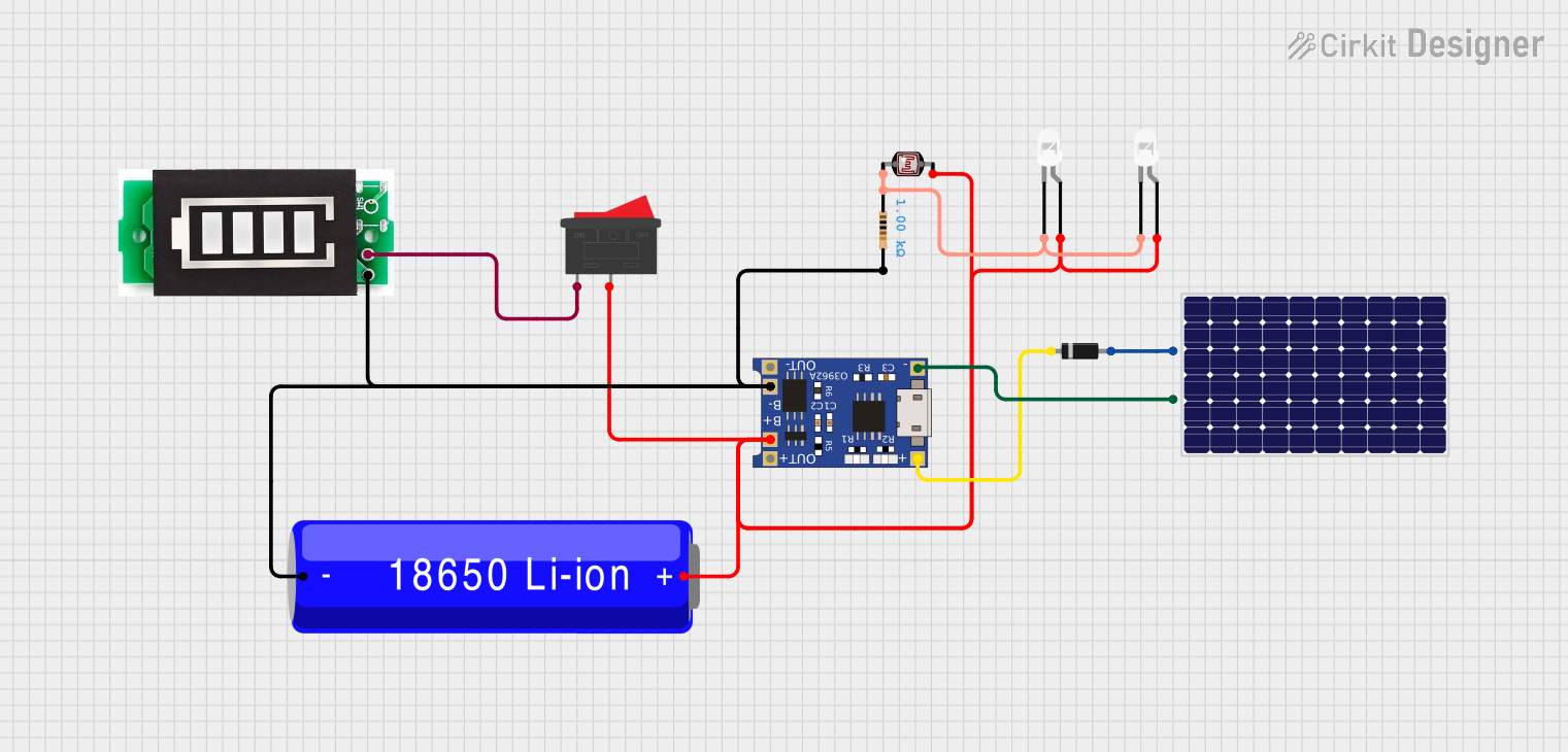
Circuit Documentation
Summary
This circuit is designed to manage the charging and discharging of a 18650 Li-ion battery using a TP4056 charging module. The circuit also includes a solar panel for charging, a battery indicator, and two white LEDs controlled by a photocell (LDR) and a rocker switch. The circuit ensures that the battery is charged efficiently and provides visual feedback on the battery status.
Component List
TP4056
- Description: Lithium-ion battery charger module.
- Pins: OUT-, B-, B+, OUT+, IN-, IN+
Solar Panel
- Description: Solar panel for charging the battery.
- Pins: +, -
Diode
- Description: Prevents reverse current flow.
- Pins: Cathode, Anode
LED: Two Pin (white)
- Description: White LED for visual indication.
- Pins: Cathode, Anode
Photocell (LDR)
- Description: Light-dependent resistor for detecting ambient light.
- Pins: Pin 0, Pin 1
Battery Indicator
- Description: Indicates the battery status.
- Pins: +, -
Rocker Switch
- Description: Switch to control the circuit.
- Pins: 1, 2
18650 Li-ion Battery
- Description: Rechargeable lithium-ion battery.
- Pins: +, -
Resistor
- Description: Resistor with a resistance of 1000 Ohms.
- Pins: Pin 1, Pin 2
Wiring Details
TP4056
B- is connected to:
- 18650 Li-ion Battery (-)
- Resistor (Pin 2)
- Battery Indicator (-)
B+ is connected to:
- 18650 Li-ion Battery (+)
- Photocell (LDR) (Pin 1)
- Rocker Switch (Pin 2)
- LED: Two Pin (white) (Anode) (both LEDs)
IN- is connected to:
- Solar Panel (-)
IN+ is connected to:
- Diode (Cathode)
Solar Panel
+ is connected to:
- Diode (Anode)
- is connected to:
- TP4056 (IN-)
Diode
Cathode is connected to:
- TP4056 (IN+)
Anode is connected to:
- Solar Panel (+)
LED: Two Pin (white)
Anode is connected to:
- TP4056 (B+)
Cathode is connected to:
- Resistor (Pin 1)
- Photocell (LDR) (Pin 0)
Photocell (LDR)
Pin 0 is connected to:
- Resistor (Pin 1)
- LED: Two Pin (white) (Cathode) (both LEDs)
Pin 1 is connected to:
- TP4056 (B+)
Battery Indicator
+ is connected to:
- Rocker Switch (Pin 1)
- is connected to:
- TP4056 (B-)
Rocker Switch
Pin 1 is connected to:
- Battery Indicator (+)
Pin 2 is connected to:
- TP4056 (B+)
18650 Li-ion Battery
+ is connected to:
- TP4056 (B+)
- is connected to:
- TP4056 (B-)
- Resistor (Pin 2)
- Battery Indicator (-)
Resistor
Pin 1 is connected to:
- Photocell (LDR) (Pin 0)
- LED: Two Pin (white) (Cathode) (both LEDs)
Pin 2 is connected to:
- 18650 Li-ion Battery (-)
- TP4056 (B-)
- Battery Indicator (-)
Code
There is no code associated with this circuit.