
Raspberry Pi Pico-Based Gas Detection System with LCD Display and Buzzer Alert
View and Edit Project In Cirkit Designer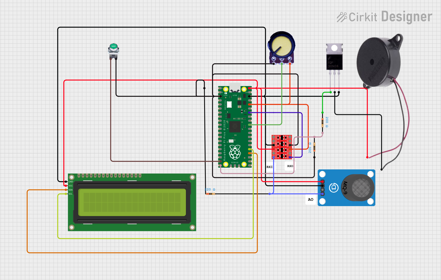
Circuit Documentation
Summary
This document provides a detailed overview of a circuit that includes a Raspberry Pi Pico microcontroller, various sensors, a display, and other components. The circuit is designed to interface with multiple peripherals and perform specific tasks as defined by the embedded code.
Component List
Raspberry Pi Pico
- Description: A low-cost, high-performance microcontroller board with flexible digital interfaces.
- Pins: 43 pins including GPIO, power, and ground pins.
Bi-Directional Logic Level Converter
- Description: A device used to safely step down 5V signals to 3.3V and step up 3.3V to 5V.
- Pins: HV1, HV2, HV, GND, HV3, HV4, LV1, LV2, LV, LV3, LV4.
MQ-9 Breakout
- Description: A gas sensor module that detects carbon monoxide and other gases.
- Pins: VCC, GND, DO, AO.
Potentiometer
- Description: A variable resistor used to adjust levels such as volume or signal strength.
- Pins: GND, Output, VCC.
Mosfet
- Description: A type of transistor used for switching and amplifying electronic signals.
- Pins: Gate, Drain, Source.
Buzzer
- Description: An audio signaling device.
- Pins: POSITIVE, NEGATIVE.
Resistor (200 Ohms)
- Description: A passive electrical component that limits current flow.
- Pins: pin1, pin2.
Resistor (220 Ohms)
- Description: A passive electrical component that limits current flow.
- Pins: pin1, pin2.
Pushbutton START
- Description: A simple pushbutton switch.
- Pins: NC, NO.
16x2 I2C LCD
- Description: A 16x2 character LCD display with I2C interface.
- Pins: GND, VCC, SDA, SCL.
Wiring Details
Raspberry Pi Pico
- pin 3: Connected to GND of Potentiometer, GND of Bi-Directional Logic Level Converter, pin1 of Resistor (200 Ohms), pin1 of Resistor (220 Ohms), and NO of Pushbutton START.
- pin 19: Connected to NO of Pushbutton START.
- pin 20: Connected to pin2 of Resistor (200 Ohms) and pin2 of Resistor (200 Ohms).
- pin 24: Connected to SDA of 16x2 I2C LCD.
- pin 25: Connected to SCL of 16x2 I2C LCD.
- pin 31: Connected to Output of Potentiometer.
- pin 34: Connected to LV1 of Bi-Directional Logic Level Converter.
- pin 36: Connected to VCC of Potentiometer and LV of Bi-Directional Logic Level Converter.
- pin 38: Connected to GND of 16x2 I2C LCD, GND of MQ-9 Breakout, GND of Bi-Directional Logic Level Converter, and Source of Mosfet.
- pin 40: Connected to VCC of 16x2 I2C LCD, VCC of MQ-9 Breakout, POSITIVE of Buzzer, and HV of Bi-Directional Logic Level Converter.
Bi-Directional Logic Level Converter
- GND: Connected to GND of Potentiometer, pin1 of Resistor (200 Ohms), pin1 of Resistor (220 Ohms), and NO of Pushbutton START.
- LV1: Connected to pin 34 of Raspberry Pi Pico.
- LV: Connected to VCC of Potentiometer and pin 36 of Raspberry Pi Pico.
- HV: Connected to VCC of 16x2 I2C LCD, VCC of MQ-9 Breakout, POSITIVE of Buzzer, and pin 40 of Raspberry Pi Pico.
- HV1: Connected to pin2 of Resistor (220 Ohms) and AO of MQ-9 Breakout.
MQ-9 Breakout
- GND: Connected to GND of 16x2 I2C LCD, GND of Bi-Directional Logic Level Converter, and Source of Mosfet.
- VCC: Connected to VCC of 16x2 I2C LCD, POSITIVE of Buzzer, and HV of Bi-Directional Logic Level Converter.
- AO: Connected to pin2 of Resistor (220 Ohms) and HV1 of Bi-Directional Logic Level Converter.
Potentiometer
- GND: Connected to GND of Bi-Directional Logic Level Converter, pin1 of Resistor (200 Ohms), pin1 of Resistor (220 Ohms), and NO of Pushbutton START.
- Output: Connected to pin 31 of Raspberry Pi Pico.
- VCC: Connected to LV of Bi-Directional Logic Level Converter and pin 36 of Raspberry Pi Pico.
Mosfet
- Gate: Connected to pin1 of Resistor (200 Ohms).
- Drain: Connected to NEGATIVE of Buzzer.
- Source: Connected to GND of 16x2 I2C LCD, GND of MQ-9 Breakout, GND of Bi-Directional Logic Level Converter, and pin 38 of Raspberry Pi Pico.
Buzzer
- POSITIVE: Connected to VCC of 16x2 I2C LCD, VCC of MQ-9 Breakout, HV of Bi-Directional Logic Level Converter, and pin 40 of Raspberry Pi Pico.
- NEGATIVE: Connected to Drain of Mosfet.
Resistor (200 Ohms)
- pin1: Connected to GND of Potentiometer, GND of Bi-Directional Logic Level Converter, pin1 of Resistor (220 Ohms), and NO of Pushbutton START.
- pin2: Connected to pin2 of Resistor (200 Ohms) and pin 20 of Raspberry Pi Pico.
Resistor (220 Ohms)
- pin1: Connected to GND of Potentiometer, GND of Bi-Directional Logic Level Converter, pin1 of Resistor (200 Ohms), and NO of Pushbutton START.
- pin2: Connected to AO of MQ-9 Breakout and HV1 of Bi-Directional Logic Level Converter.
Pushbutton START
- NO: Connected to GND of Potentiometer, GND of Bi-Directional Logic Level Converter, pin1 of Resistor (200 Ohms), pin1 of Resistor (220 Ohms), and pin 3 of Raspberry Pi Pico.
- NO: Connected to pin 19 of Raspberry Pi Pico.
16x2 I2C LCD
- GND: Connected to GND of MQ-9 Breakout, GND of Bi-Directional Logic Level Converter, and pin 38 of Raspberry Pi Pico.
- VCC: Connected to VCC of MQ-9 Breakout, POSITIVE of Buzzer, HV of Bi-Directional Logic Level Converter, and pin 40 of Raspberry Pi Pico.
- SDA: Connected to pin 24 of Raspberry Pi Pico.
- SCL: Connected to pin 25 of Raspberry Pi Pico.
Documented Code
sketch.ino
void setup() {
  // put your setup code here, to run once:

}

void loop() {
  // put your main code here, to run repeatedly:

}
documentation.txt